
MIG Welding Consumables Reduce Wire Feeding Issues and Downtime
When MIG welding consumables aren’t properly installed or maintained, it can result in wire- feeding issues and weld quality problems. Troubleshooting and correcting these challenges can cost hundreds of dollars — and hours per day — in a manufacturing operation.
As the industry faces a shortage of skilled welders and those entering the profession have less experience, it may be more common for welders to incorrectly install MIG gun consumables and liners.
Consumables that simplify the installation process can help eliminate errors, reduce downtime for changeover and troubleshooting, and decrease costs.
Learn how new consumables available in the marketplace can help address wire-feeding problems and the role they play in maximizing throughput and productivity.
The cost of poor consumable performance
Not addressing poor consumable performance can result in, among other problems, lower-quality parts and expensive rework.
Wire-feeding issues are some of the most common complaints in the welding industry. Often, improper trimming or installation of the MIG gun liner is the cause of these problems.
As with other consumables, the MIG gun liner wears out over time and must be changed periodically. Typically, replacement liners are longer than necessary and must be trimmed appropriately for the style and length of the MIG gun. Trimming the liner to the proper length can be difficult. In some cases, the welder may change the liner without taking the time to complete the proper steps of installation or may not know the proper steps.
This can result in a host of problems. A liner that is cut too short can lead to the issues a lot of welders experience: wire chatter, erratic arc and burnback. A too-long liner, which happens less frequently, results in a tight fit and can cause the wire to weave and curve as it feeds through the gun. If the operator continues to weld without diagnosing the cause of any of these problems, it may result in bad welds that require rework or result in scrap.
It seems to be common in the industry that welders typically change the contact tip at the first sign of trouble with the welding gun, and this may help for a short-term fix. But if the liner is the root cause, the problem will repeat itself, leading the welder to use more tips than if a correctly trimmed liner was installed. This increases costs due to wasted consumables and downtime for changeover.
In some operations, welders don’t install or trim liners. Instead, MIG guns are taken to a maintenance department whenever a liner must be changed. This adds downtime and costs and decreases throughput in the operation.
Error-proof liner replacement
Solutions that are designed to address liner trim length errors and poor wire feeding can reduce troubleshooting, downtime and rework — ultimately saving money.
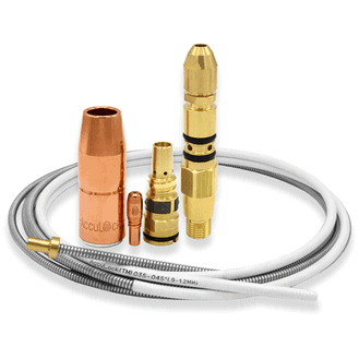
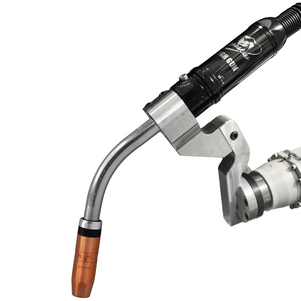
The AccuLock™ S consumables system from Bernard® take the guesswork out of liner trimming and installation in semi-automatic welding operations. The system offers an error-proof liner replacement process that eliminates measuring and incorrectly trimming liners.
In contrast to most MIG gun liners that load from the back of the gun, AccuLock S liners load through the neck at the front of the gun. The liner is then locked and trimmed flush with the power pin at the back of the gun, which eliminates the need to measure.
This design also eliminates doubt about proper liner length — and the time spent troubleshooting liner trimming issues — because operators can simply look at the back end of the gun to see that the liner is correctly trimmed and in place.
With traditional MIG guns, welders can’t see if a liner is cut too short, since the end of the liner that’s been trimmed is hidden under the nozzle and gas diffuser. A welder would have to remove all the consumables to see the liner inside the gun.
Optimize wire feeding
In addition, the system optimizes wire feeding because the liner is locked and concentrically aligned to both the contact tip and the power pin without the use of fasteners. Capturing the liner at both ends of the gun keeps the liner from extending and contracting based on gun position — and it allows for a flawless wire-feeding path.
Typically, the longer the welding gun, the more the cable bends and twists. Even when a traditional liner is perfectly cut and installed, the liner gets pushed forward and back inside the gun as it’s used, since the liner is affixed at the back end of the gun but free floating at the front end of the gun. This liner movement can result in wire chatter and erratic arc.
When the liner is affixed at both ends of the gun, as with the AccuLock S consumables system, welders are assured the liner won’t pull back, or push into the contact tip — allowing for smooth, uninterrupted delivery of the wire to the weld pool.
And because the liner is concentrically aligned with the contact tip, it creates less mechanical wear on the tip’s interior diameter, possibly leading to longer life by reducing the risk of keyholing associated with misaligned liners and contact tips. Reducing keyholing also lessens the opportunity for an erratic arc, excessive spatter and burnback, all issues that shorten contact tip life.
Maximize performance and life
Additional features of the new consumables system also contribute to optimized MIG gun performance:
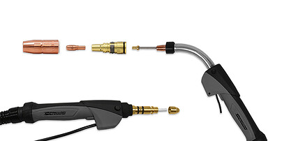
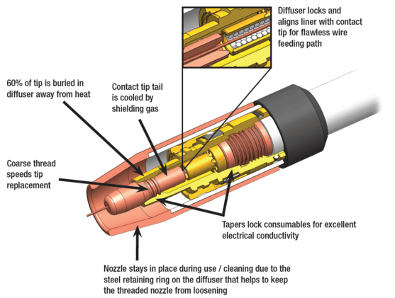
Cool, connected contact tip: Sixty percent of the AccuLock contact tip is buried in the gas diffuser to protect it from heat damage. As the shielding gas flows through the gun, it cools the contact tip tail inside the gas diffuser, which helps reduce heat and wear. These features differ from traditional tips that screw onto the gas diffuser with little to no portion of the contact tip exposed directly to the shielding gas as it exits the diffuser to the arc. A tapered design of the consumables tightly locks the conductive parts together to minimize electrical resistance and further reduce heat buildup.
Versatile nozzle: A patent-pending nozzle design allows operators to choose thread-on or slip-on — with the same nozzle part number. Typically, nozzles are either thread-on or slip-on style, a choice that often comes down to welder preference. A thread-on nozzle is locked in, while a slip-on nozzle can be adjusted to different heights and easily pulled off.
With AccuLock S consumables, the same nozzle can be used as a slip-on or thread-on nozzle, and the change is determined by using a different diffuser. This allows operations to greatly simplify their consumables inventory and changeover, with fewer parts to manage. In addition, a steel retaining ring and friction lock on the diffuser help prevent the nozzle from unthreading or loosening when it’s threaded on. This also helps eliminate the potential for gas leaks at the back of the nozzle or insufficient gas coverage of the weld — a common occurrence when traditional thread-on nozzles loosen over time.
Coarse threads: The AccuLock contact tip features coarse threads, making it less likely to become cross-threaded and also requires fewer turns to install or remove — speeding up tip replacement. One full turn disengages the contact tip from the diffuser.
Reduce wire-feeding and weld quality issues
Significant time and money can be spent troubleshooting weld quality problems and wire- feeding issues, such as erratic arc, bird-nesting and burnback. In addition, many welding operations are dealing with increasing welder retirements and turnover, which can increase troubleshooting time associated with less experienced welders installing consumables.
The AccuLock S consumables system is designed to eliminate liner trimming errors and optimize wire feeding to help operations reduce downtime, costs and rework — maximizing throughput and efficiency.
BEECHER, Ill. April 9, 2019 – Bernard has launched new versions of its BTB semi-automatic air-cooled MIG gun and Clean Air™ fume extraction gun online configurators. These mobile-friendly configurators make it easy for users to customize an industrial-duty welding gun to match their application or preferences — improving comfort and overall welding performance. Configuring a gun to users’ exact specifications can help reduce fatigue and stress, making them more productive and helping them gain high quality welds. Users can still take advantage of the configurator features offered previously, including reverse part number lookups — now with extended functionality and additional resources available. These online configurators let customers choose the specifications of their gun, including cable type and length, amperage, handle and trigger type, neck type, neck angle and length, contact tip, wire size, power pin and liner. Plus, the new Bernard® AccuLock S consumables are now available for selection in the BTB semi-automatic air-cooled MIG gun configurator. Once the configuration is complete, users receive a part number and a detailed summary of their results. In addition, users now have access to new exploded view diagrams of the welding gun and consumables, product spec sheets and an owner’s manual, as well as other relevant online resources and literature. Users can choose to print the results of their gun configuration, download them in PDF format and save them for later, or share via email, and can request more information from a Bernard representative directly on the site. They can also take the part number to their local distributor to order their gun. Learn more or access these online configurators now. # # #
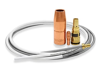
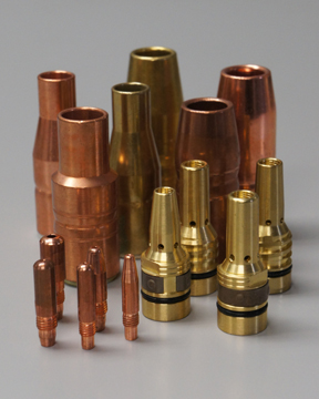
BEECHER, Ill. March 6, 2019 – Bernard has introduced its new AccuLock™ S consumables system. Building on proven MIG gun consumable technology, Bernard has added advanced design features. These features ensure higher productivity and optimized wire feeding, while also simplifying installation and maintenance. The system includes a contact tip, nozzle, gas diffuser, liner, and power pin and power pin cap. “AccuLock S consumables represent a revolutionary improvement for users of industrial MIG guns,” says Linda Ray, Vice President and General Manager. “These MIG gun consumables work together, as a complete system, improving performance and minimizing — if not eliminating — the most common gun maintenance issues.” The AccuLock S consumables are designed to solve issues associated with poor wire feeding in semi-automatic MIG welding such as bird-nesting, burnback and erratic arc. The system locks in place and concentrically aligns the liner with the power pin and contact tip. This allows for a flawless wire feeding path with no gaps or misalignments. Additionally, this does not require liner measuring during installation or replacement. Welders simply cut the liner flush with the back of the power pin for perfect liner trimming — every time. Combined, these features decrease the risk of improper installation. Moreover, this decreases the possibility of costly downtime to address poor weld quality or liner replacement. Adding to the ease of installation, the contact tips feature coarse threads that easily mate with the gas diffuser, lessening the chance of cross-threading and speeding contact tip replacement. By design, the Acculock S MIG gun consumables reduce heat buildup, improving product life. Sixty percent of the contact tip is buried in the gas diffuser to protect it from heat damage. The shielding gas helps cool the contact tip tail. The tapered design of the consumables tightly lock conductive parts together to minimize electrical resistance and further reduce heat buildup. As a complement to the AccuLock S MIG gun consumables system, AccuLock MDX™ consumables launched with the new Miller® MDX MIG guns in February 2019. AccuLock R consumables for robotic welding applications will release under the Tregaskiss® brand name later in 2019.
Every operation wants to avoid downtime, as well as the cost for troubleshooting problems in the robotic MIG welding cell. But sometimes issues happen, whether it’s due to equipment failure or human error. Since most companies invest in welding automation to boost throughput and profitability, getting a robotic welding cell back online as quickly as possible is critical to production and the bottom line. The first things to consider are whether anything has changed in the welding process or with the equipment, or if the operator has recently reprogrammed the robot. In many cases, evaluating the most recently changed variable can help you pinpoint an issue’s cause. After that, analyzing some of the most frequent sources of trouble in the robotic weld cell can help you get to the root of the problem sooner. Consider these five common issues and ways to fix them. A: The material being welded and the parameters being used affect welding consumables’ longevity. But if it seems that nozzles, contact tips, diffusers or liners aren’t lasting their typical life or are performing poorly, there could be several causes. Check all connections between welding consumables and tighten them as needed. A loose connection increases electrical resistance and generates additional heat, which can shorten consumable life and cause poor performance. It’s especially important to ensure consumables are properly tightened when the application involves long welds or welds on thick materials, since any rework due to quality issues will cost more time and money in these cases. Common contact tips issues, such as burnback, are often caused by a too-short liner. Always follow the manufacturer’s instructions for liner trimming and installation, and use a liner gauge to confirm length when possible. Over time, debris and spatter buildup inside the liner can contribute to shortened contact tip life. It’s important to create a schedule for changing liners, just as you would for other consumables. If you’re frequently experiencing weld defects like porosity or lack of penetration, this can also stem from a consumables issue. Make sure the contact tip and nozzle are free of debris and replace them as needed. A: Erratic or poor wire feeding in robotic welding is a common issue that can ultimately result in poor weld quality. Poor wire feeding can have many causes. Cutting a liner too short is particularly problematic when robotic welding with smaller diameter wires, which have less column strength. Extreme articulation of the robotic MIG gun can also lead to poor wire feeding. Program the robotic MIG gun cable to stay as straight as possible. The robot may not weld quite as fast, but proper gun orientation helps minimize downtime for feeding problems. Excessive conduit length and multiple bends or junctions can cause poor wire feeding as well. With the drive rolls open, you should be able to pull the wire through the contact tip by hand with minimal effort. If you need to pull with two hands or put your bodyweight into the process, that indicates interference with the wire path between the wire drum and the contact tip. Check for bends tighter than 90 degrees, multiple junctions between sections of conduit or worn conduit sections that can increase drag on the wire. Ideally, the conduit between the drum and the wire feeder should be less than 20 feet, with no junctions or tight bends. Improper drive roll selection and tension setting can also lead to poor wire feeding. Consider the size and type of wire being used and match that to the drive rolls. Inspect drive rolls for signs of wear and replace them as necessary. A: Whether you have a through-arm robotic welding system, where the cable is routed through the robotic arm, or a standard over-the-arm robotic welding system, premature power cable failure can happen. A power cable that becomes kinked or worn can fail and short-out against the robot casting, leading to costly repairs. To help prevent premature cable wear, consider the programmed path of the robot as well as the power cable’s length. If the robot’s movements cause the cable to bunch up or kink, it can cause the power cable to fail. If the power cable rubs against tooling or catches on components during the programmed cycle, this can also cause premature failure. A: In robotic welding, TCP refers to the location of the end of the welding wire with respect to the end of the robot arm. If you are experiencing inconsistent welds or welds that are off-location, this may stem from a problem with TCP. If the robotic MIG gun neck is bent or damaged during a collision in the weld cell, this can result in TCP issues. Use a neck-checking fixture or neck alignment tool to help ensure proper angle of the neck bend. Also, be sure the neck and consumables are installed and torqued properly. Failure to do so may affect TCP. However, a problem with off-location welds isn’t always caused by TCP issues. Improper fixturing or part variations may also be the root cause. If a TCP check using the robotic program turns up with no issues, a part or position variation is the likely culprit. A: Companies often implement peripherals, such as reamers or nozzle cleaning stations, to optimize robotic welding performance and get more life out of consumables. But a problem with the reamer can cause spatter buildup on the consumables. Reamers can perform poorly for three common reasons: Problems in the robotic welding cell can be as simple as a loose contact tip or more complex like incorrect TCP. Understanding the steps for proper troubleshooting helps narrow down potential causes and can prevent replacement of components that don’t need replacing — so the operation can save money and quickly get back to producing quality parts. Learn more from the Tregaskiss Troubleshooting Guide.
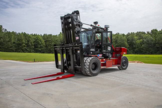
Taylor Machine Works Inc. has spent over 90 years building a reputation by engineering and producing exactly what its customers need. The company manufactures more than 85 models of powered industrial trucks, including forklifts and material handling equipment for a range of industries. “We manufactured roughly 750 pieces of rolling stock last year and 40 percent to 50 percent of that is highly customized,” said Matt Hillyer, director of engineering for Taylor, based in Louisville, Mississippi. “Our job is to build products that answer the customer’s needs.” Taylor’s “Big Red” forklifts, featuring the company’s distinctive “Big Red” logo, can handle material weighing up to 125,000 pounds — everything from palleted goods and empty shipping containers in waterfront shipyards to equipment encountering brutal hot and cold environments. Many of Taylor’s customers are small operations with from one to three pieces of equipment. Just one piece going out of service reduces production capacity by a large percentage. “Having high durability, high return on investment and low cost of ownership, those are all very imperative to our customers to make them successful,” said Hillyer. “It’s important for us not only to make custom products that are advanced in technology or state-of-the-art, but we also have to make products that are very simple, easy to work on and have lots of uptime. That’s what our customers are looking for.” Taylor employs some of the best welders in the business to meet those customer demands, but even great welders can’t overcome their tools’ limitations. When Taylor decided to try Bernard® semi-automatic MIG guns and Centerfire™ consumables, they discovered their talented team could take productivity up a few notches —and still gain the best quality. Making the change “Before we changed to Bernard welding products, we didn’t really know we were having a problem,” said Steve Nazary, quality assurance supervisor at Taylor. “When we started using Bernard [MIG guns and consumables], we found that they were much easier and more economical to use for our process.” Bernard semi-automatic MIG guns at 400, 500 and 600 amperages delivered more business benefits. Savings on service repair. “We can replace the liners, the tips, the nozzles” Nazary explained. “You can replace everything on a Bernard gun instead of throwing it away and buying a new one.” The previous guns Taylor used could not be repaired and components weren’t replaceable, resulting in increased costs for new purchases for their large manufacturing operation. Productivity-boosting ergonomics. “The Bernard MIG guns have a better handle on them,” Nazary said. “It fits your hand better. It has an easier trigger to pull. It doesn’t get as hot as the guns we were using before. We were using some handles before that got so hot, you couldn’t hold them anymore.” “Those twisty necks, as I call them, we can loosen them and change the angle to get in harder places. And you can reset them back straight, turn them on any angle. The employees love them.” Easier-to-use rotatable necks. Guns with multiple neck position options that are all easy to adjust let Taylor welders operate comfortably and precisely in more situations. Rather than turning the entire gun to get the right position to reach a weld joint, welders simply adjust just the neck of the gun to a better angle. Nazary added that it’s also easy to change necks on the Bernard MIG Guns to reach into tighter spaces. “We have multiple necks and they only take two or three seconds to swap them out,” he said. Centerfire™ consumables also proved to last much longer than products Taylor had used previously, reducing the need to change contact tips from multiple times per day to just once a day, on average. These consumables feature a non-threaded contact tip that is tapered at the base to seat easily in the gas diffuser. The result is better heat dissipation and a longer life. Plus, they are quick to change over. “We can change the Centerfire consumables with ease. We don’t have to have tools. You just twist the nozzle off, pull it off and pop another contact tip in and twist the nozzle back on,” said Nazary. Centerfire consumables also provide better gas flow for better welds and less rework. “With the other consumables that we were using, you would get different gas flows,” said Nazary. “With the Bernard products, we have consistent flow all the time.” “It’s absolutely imperative to make our products successful for the customer,” said Hillyer. “We also look to our suppliers, like Bernard to provide us with the best technology. They help us incorporate the right technology to make sure that we do have the most durable truck on the market.”
Implementing robotic welding can significantly improve a manufacturing operation’s productivity and weld quality, but what are the robotic welding basics you should know to be successful? From choosing the right welding wire to establishing proper tool center point (TCP), many variables play a role in optimizing robotic welding cells to produce the best results. Shaving even a few seconds from each weld cycle can save time and money. Minimizing the unplanned downtime for adjustments or repairs in the weld cell can also have a substantial impact on your bottom line. Success with robotic welding requires a well-researched plan. The more planning done upfront, the less time and money you could spend later making fixes and process improvements. Learning some basic tips for setting up a robotic weld cell can help to establish a repeatable and consistent process — so your operation can produce quality welds, reduce rework and maximize its investment. Proper weld settings for the application are based on factors including wire size and material thickness. Some welding power sources offer technology that allows welders to simply input the wire size and material thickness, and the machine will suggest recommended parameters for the application. Without this technology, finding the correct parameters can involve a bit of trial and error. Sometimes the robot manufacturer, welding power source manufacturer or system integrator can assist in choosing and testing specific materials to provide a starting point for the proper welding parameters. Utilize the experience of these partners to help you arrive at the best starting point and be prepared for the future. The choice of filler metal for a robotic welding system can significantly impact productivity, weld quality and the overall investment. Selecting the right wire for a robotic application is typically based on the material type and thickness, as well as the expected outcomes for the welded part. Welding equipment and filler metal manufacturers often offer charts to help you match a welding wire to your process needs. While solid wire has been the industry standard in robotic welding for many years, metal-cored wire is an alternative that can offer productivity and quality improvements in some applications, particularly in the manufacture of heavy equipment and automotive exhaust, chassis and wheels. However, be aware that each wire type offers pros and cons for certain applications, so it’s important to research the type that is best suited to your application. Robotic welding guns and consumables, including the nozzle, contact tip and gas diffuser, have a huge impact on performance in a robotic weld cell. The right combination can reduce unplanned downtime and improve overall efficiency of the cell. Be sure the welding gun is rated with enough duty cycle and amperage for the application. To avoid excessive wear and premature failure, the gun should not rub against any part of the system or another robot in applications where multiple robots are being used on the same tooling. Robotic welding systems typically operate at higher duty cycles than semi-automatic welding applications, and they may utilize transfer modes that are especially harsh on consumables. Consider using heavy-duty consumables that are more heat-resistant than standard-duty consumables. Chrome zirconium contact tips or tips specifically designed for pulsed welding processes are good options. In addition, ensure all consumables are properly installed and tightened. Improper or loose connections produce more electrical resistance and heat that causes faster consumable wear with premature failures. Another common failure in robotic welding is improper liner installation. Always follow the manufacturer’s directions for liner installation and cut length. A liner that is cut too short can cause premature failures of other consumables in the system. Make sure there is good cable grounding in the weld cell to help prevent potential problems as the cell ages. There are two cables running from the welding power source; one is attached to the wire feeder and the other is grounded to the tooling. Often, these cables are long and run from the shop floor to an elevated platform or through wire trays. The section of cable running up the robot or running to a positioner will constantly move — causing greater wear over time. Using a junction with high-flex ground cable at the base of the robot or the workpiece can save time and money in downtime and repair. With this solution, there is only a 6-foot section of cable to replace when it wears out, rather than replacing possibly 50 feet or more of ground cable that runs all the way back to the power source. However, keep in mind you should have as few breaks or junctions in the grounding cable as possible to maintain a better electrical connection. When mounting a ground cable to the welding workpiece, it can be helpful to use copper anti-seize lubricant, sometimes referred to as copper slop. This supports the transfer of electrical current and helps prevent the mounting point from fusing together or deteriorating over time. The lubricant can be useful in all areas where there may be grounding current running through pins or any other semi-permanent contact points. Proper cable management for the guns can also greatly extend cable life. The more any cable bends and flexes, the more wear and tear will occur — ultimately shortening cable life due to high heat and resistance. Work to minimize cable bending and flexing in your robotic process and tooling design. For repeatable and consistent weld quality, it’s critical to establish and maintain proper TCP. Welding operations can set their own standards for the acceptable amount of TCP drift, depending on the application and type of weld being made. When considering the tolerance of TCP variation, an acceptable starting point can be half the thickness of the wire diameter. Many robotic systems today can use touch-sensing features to monitor TCP and determine how far it has moved from the original programmed settings. If a gun is determined to be out of the acceptable TCP range, the gun neck can be removed and recalibrated offline to factory specifications with a neck straightening fixture. Some systems also provide the capability to adjust TCP automatically with the robot. A third option is to leave the gun in place and adjust the robot teaching to accommodate the modified TCP. This is the most time-consuming solution and, therefore, often not acceptable for the manufacturing operation. It also requires the need to reprogram the robot if new factory specifications for TCP or a new neck are ever put into place — which is why this method is typically the last resort. Set a schedule or standard for checking TCP, whether it’s every weld cycle, once a shift or even every time the torch goes through a reamer cycle. The length of time between checks is a matter of preference and weighing your priorities. It can be time-consuming to check every weld cycle, but this can save money in lost scrap and rework if a problem is found before welding occurs. The initial programming of the robot’s welding path can also involve much trial and error. When programming the path, consider the application, material type, welding process being used and gap size that must be filled. The weld quality and amount of spatter created are also impacted by the travel angle and whether it’s a pull or push weld. It can take time to dial in the correct path to achieve the desired quality. After setting the home positions in the robotic program, it’s recommended to have the robot move to perch points or ready-to-enter points that are safely away from any potential collision points, so the system can move quickly with air cut moves to and from these points. When programming the robot to move to a weld, it’s common to set the approach point just above the weld start location. Have the robot approach the start location at a slower and safer speed with the arc on. This approach position provides a good lead-in and typically won’t require adjustment unless the weld is relocated. Some robotic welding systems include technology that aids in setting the initial robot path. The robot’s welding location can play a role in premature failure of the gun. If the robot is welding with a lot of flex in the gun at a tight angle, this can cause it to fail much faster. Minimizing robot axes five and six during welding can help extend gun life by reducing wear. Proper part fit-up in the upstream process is critical to consistent weld quality and robot path programming. Inconsistent fit-up or large gaps between the parts lead to weld quality issues such as burn-through, poor penetration, porosity and others — resulting in additional unplanned downtime to deal with these problems. Large gaps between the parts may also require double weld passes, adding to cycle times. From wire and consumable selection to proper cable management and TCP, many variables play a role in weld quality and ultimately, the success of your robotic welding system. Careful planning at the start of the process and continued monitoring of these key factors helps optimize performance — so you can get the most from your robotic welding investment.
APPLETON, Wis. (February 6, 2019) — Miller Electric Mfg. LLC has introduced its new MDX™ series MIG guns. Designed with operator comfort in mind, these MIG guns feature a durable and ergonomic handle with a rubber overmolding for improved grip, while the addition of a ball and socket handle swivel reduces fatigue. AccuLock™ series consumables add to the performance of the gun, providing a flawless wire feed path. The front-loading liner locks in place (no need for set screws) and aligns concentrically with both the contact tip and power pin to optimize wire feeding. Error-proof liner trimming, with no measuring required, reduces burnbacks, bird-nesting and erratic arc caused by liners that are too short, minimizing downtime for troubleshooting or rework. The MDX series includes three models: MDX-100, MDX-250 and MDX-250 EZ-Select™. These guns are all compatible with Miller AccuLock MDX series consumables, and the MDX-250 and MDX-250 EZ-Select guns are also compatible with Bernard AccuLock S consumables. Both AccuLock series feature tapered connections between the contact tip, gas diffuser and neck to maximize electrical conductivity for longer product life. Coarse thread on the contact tips speeds replacement by mating easily with the gas diffuser and lessens the risk of cross-threading. Bernard® AccuLock S consumables are an excellent upgrade to increase durability and consumable life when welding with MDX-250 or MDX-250 EZ-Select guns in heavier industrial environments. They also simplify consumable inventory for operations using a mix of Miller MDX and Bernard MIG guns. Miller offers conversion parts to retrofit older style Miller MIGmatic M-Series guns with AccuLock MDX and AccuLock S consumables. M-Series consumables will not be compatible on the new MDX series MIG guns. The MDX series guns will be made available on multiple Miller power sources. The MDX-100 is rated at 100 amps. It pairs with the following: The MDX-250 contains increased copper in the cable, is pulse welding capable, and can be used with CV waveforms. It is compatible with the following: The MDX-250 EZ-Select gun features trigger program select that allows the user to select up to four weld programs by tapping the MIG gun trigger, saving time for walking to the machine to make changes. To help avoid errors, the gun features LED lights on the handle to indicate the weld program that is currently selected. It works with the following: For more information, visit MillerWelds.com/mdx.
January 8, 2019 Our product offering is regularly assessed to ensure focus on customer needs and opportunities to innovate our product portfolio, so we can continue to deliver sustainable value to our customers. Accordingly, due to low demand, the following products will be discontinued: Effective January 8, 2019, all legacy F-Gun MIG gun part numbers and all F-Gun series service parts will be discontinued and no longer available for sale. The following 600 amp Bernard® BTB semi-automatic air-cooled MIG gun models (with T series straight handles and locking triggers) are recommended replacement options:
January 25, 2019 To continue delivering sustainable value to our customers, we regularly assess our product offering to ensure focus on customer needs and opportunities to innovate our product portfolio. Accordingly, due to low demand, select Tregaskiss® nozzles will be discontinued. Effective March 1, 2019, all nozzles listed in the chart below will be discontinued as inventory depletes, and effective March 30, 2019, these nozzles will no longer be available for sale. Click here to download the above list in PDF format.
November 1, 2018 Bernard is proud to introduce new AccuLock™ S consumables, a system designed to address liner trim length errors and erratic wire feeding. Important Note: Most components of the AccuLock S consumables family are currently available. The complete offering will be coming soon. The AccuLock S liner is locked and concentrically aligned to both the contact tip and the power pin without the use of fasteners, which provides a flawless wire-feed path that guarantees smooth, uninterrupted delivery of the wire to the weld puddle. Plus, the liner replacement process has been error-proofed so you can trim your liner accurately and easily every time, with no measuring. The AccuLock S consumables system requires all AccuLock components: contact tip, diffuser, nozzle, liner, neck insulator, power pin and power pin cap.
MIG welding, like any other process, takes practice to refine your skills. For those newer to it, building some basic knowledge can take your MIG welding operation to the next level. Or if you’ve been welding for a while, it never hurts to have a refresher. Consider these frequently asked questions, along with their answers, as welding tips to guide you. The welding wire size and type determines the drive roll to obtain smooth, consistent wire feeding. There are three common choices: V-knurled, U-groove and V-groove. MIG welding wires vary in their characteristics and welding parameters. Always check the wire’s spec or data sheet to determine what amperage, voltage and wire feed speed the filler metal manufacturer recommends. Spec sheets are typically shipped with the welding wire, or you can download them from the filler metal manufacturer’s website. These sheets also provide shielding gas requirements, as well as contact-to-work distance (CTWD) and welding wire extension or stickout recommendations. Contact tip recess, or the position of the contact tip within the MIG welding nozzle, depends on the welding mode, welding wire, application and shielding gas you are using. Generally, as the current increases, the contact tip recess should also increase. Here are some recommendations. The shielding gas you choose depends on the wire and the application. CO2 provides good penetration when welding thicker materials, and you can use it on thinner materials since it tends to run cooler, which decreases the risk of burn-through. For even more weld penetration and high productivity, use a 75 percent argon/25 percent CO2 gas mix. This combination also produces less spatter than CO2 so there is less post-weld cleanup. For all positions, it is best to keep the welding wire directed toward the leading edge of the weld puddle. If you are welding out of position (vertical, horizontal or overhead), keeping the weld puddle small provides the best control. Also use the smallest wire diameter that will still fill the weld joint sufficiently.
November 1, 2018 Customers may notice that some Bernard® parts and consumables are arriving in different bags. We transitioned to a newly designed Bernard branded white bag design. In addition to changing the artwork layout and color of the bags, the overall usability has also been improved. These new white bags offer a clear window on the printed side of the bag to make visual product identification easier. To increase the hanging capacity of the bags, we’ve added a second hanging hole on our larger bags and a new double-sealed header on all bag sizes. The sombrero shaped hanging holes provide compatibility with a wider variety of hook sizes and shapes.
November 1, 2018 Customers may notice that some Tregaskiss® parts and consumables are arriving in different bags. We transitioned from a black bag design to a white bag design. This new white bag design has a clear window on the back side of the bag to help make visual product identification easier, and the durability and hanging holes remain the same as our previous black bag packaging.
For structural applications, some contractors have made the switch from stick welding to self-shielded flux-cored welding to increase productivity and give themselves a competitive edge. Self-shielded flux-cored welding offers much greater travel speeds and deposition rates compared to stick welding, while also eliminating the frequent stopping and starting required to change out stick electrodes. For contractors considering this conversion, there are some key factors to keep in mind to help choose the right self-shielded flux-cored welding gun for the job — and to use and maintain it properly. Gun options such as heat shields, configurable necks and adjustable cable lengths can help improve weld quality, efficiency and operator comfort in self-shielded flux-cored applications. Self-shielded flux-cored welding is becoming more common on jobsites for several reasons. In addition to the greater productivity and deposition rates of the process, it also doesn’t require a shielding gas to protect the weld pool, eliminating the hassle and cost of buying and storing gas containers on the jobsite. Not using shielding gas also eliminates the need to set up tents or wind shields to protect the weld from the elements and the need to use specialty nozzles to control gas flow as is common with a gas-shielded flux-cored process. Some training may be required for welders who are used to the stick process. The different ergonomics of the self-shielded flux-cored gun compared to the stick electrode holder require approaching the weld from different angles and using different travel angles and pressure. When stick welding, the operator typically begins with the electrode (and therefore his or her body) farther from the weld. As the rod shortens during welding, the welder gets physically closer to the weld, applying pressure to the stick electrode as it melts into the weld pool. In self-shielded flux-cored welding, the welder stays in the same spot, maintaining a consistent distance between the contact tip and the weld pool. The proper contact-tip-to-work distance depends on the application, but at least 1/2 inch is a good rule of thumb. Self-shielded flux-cored welding can be prone to slag inclusions if proper technique isn’t followed. Regularly inspect the contact tip to ensure it’s free from spatter and debris buildup, which helps ensure smooth wire feeding. Properly clean the weld between passes. Welding guns for self-shielded flux-cored applications are available in various configurations. Choosing the right gun can help contractors tailor it to their specific needs and applications. Consider these features: Heat shield: One of the most common features on self-shielded flux-cored welding guns is a hand guard or heat shield, which is available in different sizes. In applications that require access to a corner joint, choosing a smaller guard increases maneuverability and provides more access. When welders need to run at a higher voltage and deposit more filler metal into the weld, using a larger guard helps deflect the higher heat. Neck lengths and bends: Gun necks are available in varying lengths and bend angles. A slimmer neck provides a better view of the weld pool and improved access to tight areas, for example. A shorter neck typically provides more control compared to a longer neck. Lightweight, rotatable necks can also reduce operator fatigue and improve weld visibility. Replaceable or fixed cable liner: Some self-shielded flux-cored gun models are available with either a replaceable cable liner or a fixed cable liner. A replaceable cable liner provides benefits in harsh and demanding environments, since self-shielded flux-cored welding can be hard on equipment and consumables. Replaceable power cable liners provide quick and easy cable maintenance and can extend product life since welders can change out components that experience high levels of wear. In addition, choosing a replaceable cable liner with internal trigger leads means there is no external trigger cord that can catch on surrounding objects. Conversely, fixed cable liners tend to be larger, which can be an issue when welding in corners or tight spaces. Dual schedule switch: A self-shielded flux-cored gun with an optional dual schedule switch allows for wire speed adjustment while welding. In some guns, this switch is integrated into the handle to keep it protected from spatter. The ability to toggle between weld parameters easily — without having to stop welding and change settings — saves time and improves productivity. There are ways to extend the life of the gun and consumables. The necessary frequency of gun and consumable maintenance depends on the application and the welding environment. Conduct routine checks to ensure front-end consumables are in good shape and all connections are tight. This helps keep heat resistance low and ensures proper electrical conductivity so the gun and consumables last longer. Consider using a rotatable gun neck with a collet-style connection, which makes it easier to drop the neck in and tighten it. Consumables that use compression fittings also provide more efficient energy transfer and less overheating to help extend product life. Be sure to keep the contact tip clear of spatter buildup and inspect the tip for signs of wear or keyholing, and also inspect the cable for any damage or nicks. While the self-shielded flux-cored process is capable of welding material with dirt, oil or mill scale, remember that better surface preparation delivers better results in any welding application. Properly cleaning the base material will help produce better welds. Because flux-cored welding produces a slag and spatter, there is also a need to remove the slag between passes and for post-weld cleaning. Be aware that travel angles beyond 20 or 25 degrees can increase spatter and arc instability. With flux-cored welding, it’s recommended to use a drag technique with a travel angle of 5 to 15 degrees. As more contractors look for ways to increase productivity and efficiency on the jobsite, the use of self-shielded flux-cored welding grows. Choosing a welding wire designed to improve a weld’s chemical composition or deposition rates can provide even more benefits. The self-shielded flux-cored process can be a good alternative to stick welding in many outdoor applications that boosts productivity and reduces costs.
Is your robotic welding operation costing time and money for problems like burnbacks, premature contact tip wear, loss of tool center point (TCP) or other issues? These common failures in robotic welding can be costly, resulting in downtime and unplanned part replacement. Even issues that seem minor, such as the wire sticking to the contact tip and forcing tip replacement, can cost thousands of dollars per day when you consider lost consumables, cell downtime and labor costs for changeover. Beyond the time and money spent on minor issues, there’s also the risk of catastrophic failure that could short out the robot or damage system electronics — potentially costing tens of thousands of dollars. Avoiding common failures is often a matter of proper weld cell setup and robot maintenance, in addition to following some best practices for consumable installation. Operator training is also critical in preventing common failures in robotic welding. One of the most common failures in a robotic weld cell is burnback and premature contact tip wear. The top cause of burnback is an improperly trimmed gun liner. When a liner is too short, it won’t seat in the retaining head properly, causing burnback. To avoid this problem, follow the manufacturer’s recommendations for proper liner trimming. It’s also helpful to choose a high-quality liner designed for accurate liner trimming and installation. Burnback is one cause of premature contact tip wear, but wear can also result from other factors. Using low-quality wire with a lot of cast can be another cause, as it quickly wears out the contact tip compared to using a better-quality, straighter wire. Drive rolls that are too tight can also cause wire cast issues that wear the contact tip faster. Improper welding parameters — such as welding too hot or too cold — can also wear contact tips prematurely and force more frequent changeout. Adjust parameters accordingly to minimize this problem. The main cause of broken cutter blades in robotic welding is incorrect positioning or too much angle of the robotic MIG gun nozzle as it enters the reamer for cleaning. For example, if the depth of the Z axis is too deep, the torch will go in too far and may cause the reamer blades to break. To prevent this, the nozzle should be concentric to the cutting blade. Use an angle finder app on your smartphone or tablet to ensure the positioning is straight up and down on the X and Y positions. Also, be sure the insertion depth on the nozzle goes past the gas holes on the diffuser. Drag marks on the diffuser or contact tip are signs of wear that mean the nozzle is not concentric to the reamer blade. Proper setup and positioning also helps ensure consistent coverage of anti-spatter spray on the nozzle. Broken cutter blades can also result from excessive spatter in the nozzle, which can be caused by poor spraying setup, incorrect weld parameters or incorrect torch angle. Spatter sticks to spatter and as the buildup grows, it can break the cutter blade as it tries to enter the nozzle. Keep in mind that you may need to ream and spray more frequently depending on the application and the material being welded to avoid some of these issues. Problems with the contact tip, nozzle, reamer and excessive spatter can also result when there is poor grounding in the weld cell. Regularly inspect all cables for damage and be sure the ground cables are securely connected. When TCP is lost in a robotic weld cell, one common cause is improperly installed consumables. A cross-threaded consumable will angle the contact tip where it meets the retaining head, causing the tip to bend and disrupting TCP. Be sure to tighten consumables to the manufacturer’s torque specifications. The general rule of thumb is one quarter turn past finger tight. A worn clutch can also cause loss of TCP. The clutch system helps prevent damage to the robot or gooseneck during tooling collisions. After repeated incidents, the clutch may allow a few degrees of movement in either direction, which throws off TCP. Consider using a neck inspection fixture, which tests and adjusts the tolerance of a robotic MIG gun’s neck to the TCP so you can readjust it after an impact or after bending due to routine maintenance. In a robotic weld cell, the disc functions as a buffer between the mount and the robot arm. It’s designed to be sacrificial; if the torch, mount or robot arm collide, the disc will absorb the bulk of the impact. However, the disc can be broken when it’s hit hard enough by the neck or torch mount, so replace it if damaged. Set the robot path correctly to avoid neck collisions. Overtightening the screws can also break or crack the disc and cause it to fail. Discs have torque specifications from the manufacturer. Use those specifications to prevent overtightening and reduce the risk of cracking. The specification sheet also describes the order in which the screws on the disc should be tightened. Robotic weld cell failures can also be caused by programming errors. If the robot’s path to the tooling is programmed incorrectly, the arm can come into contact with the tooling or the weld cell wall. The torch rubbing on the cell wall can create holes in the cable. In addition, if the neck frequently hits the tooling, this can bend the neck or cause the disc to break. To prevent these issues, program the robot so the arm is clear of the tooling and doesn’t encounter the tooling or the wall. Preventive maintenance is key to keeping a robotic welding system and its components performing optimally — and extending consumable life. Regularly check all cables to make sure they are secure, free of damage and not rubbing anything. Establish and follow a schedule for liner changeover. The required frequency of liner changeover depends on what type of filler metal is being used, what material is being welded and shop conditions. A shop that is very dusty means liners will clog faster, for example. Consult the manufacturer’s maintenance recommendations and follow a preventive maintenance checklist to ensure all the system’s components and parts remain in good working order. Using high-quality robotic MIG guns and consumables also helps prevent problems that can arise in the weld cell. Taking steps to avoid common failures in the robotic weld cell allows your operation to improve productivity, reduce consumable costs and ensure consistent part quality.
September 12, 2018 To continue delivering sustainable value to our customers, we regularly assess our product offering to ensure focus on customer needs and opportunities to innovate our product portfolio. Accordingly, due to low demand, the following products will be discontinued: Effective September 30, 2018, all standard and special Tandem MIG guns and necks will be discontinued and no longer available for sale. All service parts for Tandem torches will be available for sale until December 31, 2018, at which time all service parts for Tandem torches will be discontinued. Click here for a list of affected part numbers.
September 12, 2018 To continue delivering sustainable value to our customers, we regularly assess our product offering to ensure focus on customer needs and opportunities to innovate our product portfolio. Accordingly, due to low demand, the following products will be discontinued: Effective December 31, 2018, all service parts for Tregaskiss® quick-change water-cooled (QCWC) and Tregaskiss keyed water-cooled (KWC) robotic MIG guns (discontinued October 1, 2008) will be discontinued and no longer available for sale. Click here for a list of affected part numbers. Note: Availability and list prices of replacement parts for the affected products are subject to change without notice.
WINDSOR, Ontario. September 11, 2018 — Tregaskiss has expanded its TOUGH GUN® TA3 robotic air-cooled MIG gun offering to include configurations for additional through-arm style robot models in the marketplace. These include: In addition to being fully customizable according to robot make and model, most TOUGH GUN TA3 robotic MIG guns can be configured with the desired solid or clutch mount/wire brake/air blast combinations, neck, nozzles, contact tips and more at Tregaskiss.com/ConfigureMyGun. The guns have been designed with precision and reliability in mind and feature the unique low-stress robotic (LSR) unicable, which incorporates a rotating power connection for stress-free rotation that helps extend the life of the cable. A specially engineered neck clamp improves the consistency and durability of the clamping force, while a wide selection of standard necks expands the tool center point (TCP) options and variety of working envelopes. The TOUGH GUN TA3 robotic air-cooled MIG guns are compatible with Tregaskiss® consumables and with the QUICK LOAD™ liner AutoLength™ system — a system that helps rectify wire feeding and quality issues associated with incorrect liner length. Housed inside the power pin, the spring-loaded module applies constant forward pressure on the liner, keeping it seated properly in the retaining head and allowing up to one-inch forgiveness if the liner is too short.
When using anti-spatter liquid in a robotic weld cell, there are steps you can take to optimize the application of the spray. The addition of an anti-spatter sprayer to a nozzle cleaning station helps ensure delivery of consistent amounts of anti-spatter liquid, leading to longer consumable life, better weld quality and higher productivity. You can also add an anti-spatter multi-feed system to help lower costs, minimize downtime and increase safety. These systems eliminate the need to refill spray reservoirs frequently by feeding up to 10 reamers from a single 5- or 55-gallon drum of anti-spatter liquid. Position the robotic MIG Gun and front-end consumables correctly. Aligning these in the right location for the ream cycle and anti-spatter liquid application helps apply the liquid uniformly. Always follow the manufacturer’s instructions for proper setup based on the nozzle bore size. If the sprayer is too far away from the nozzle, it will not provide adequate coverage to prevent spatter buildup. If the nozzle and sprayer are too close, too much spray may saturate the nozzle insulator, which can lead to premature failure. Spray for about a half-second. If you need to spray longer, it usually means the sprayer is too far away. Never spray the liquid for three or more seconds, as it can harm the consumables, cause residue buildup in the weld cell (and with it slippery surfaces) and may damage power sources by adversely affecting the electrical circuits. Use a spray containment unit. This 3- to 4-inch unit fits over the spray head on the anti-spatter liquid sprayer to capture excess anti-spatter liquid. After the spatter has been cleared from the nozzle during the reaming cycle, the nozzle docks on the spray containment unit. An opening at the top of the cylinder allows the anti-spatter liquid to spray onto the nozzle while an O-ring seals the nozzle in place; only the outside edge and inside of the nozzle are sprayed. To care for a spray containment unit, routinely remove any spatter or debris from the bottom and clear the screen or filter inside the unit of contaminants using clean, compressed air.
Having the right products for your welding application impacts quality and productivity. Anti-spatter liquid is no exception. When selecting an anti-spatter liquid for a robotic welding application, be certain that it offers the following attributes: • Uniform coverage to protect the entire nozzle A water-soluble compound, like Tregaskiss® TOUGH GARD® anti-spatter liquid, is a popular option. This liquid is non-toxic and eco-friendly, helping companies to improve employee safety and provide a cleaner work environment. Oil-based anti-spatter liquid is also available in the marketplace, but is generally less desirable to use because it is more difficult to clean up if it settles on fixtures or other parts in the weld cell. Oil-based anti-spatter liquid is not always compatible with all nozzle cleaning stations, and it can clog this equipment. Even though the more popular water-based anti-spatter compound is non-toxic, you should always take care when handling and using it. This article is the second in a three-part series focused on the use and benefits of anti-spatter liquid. Read article one, Spatter in Welding: Should You Consider Anti-Spatter Liquid? and article three, Anti-Spatter Sprayer: How to See the Best Results
Are you losing money and arc-on time for excessive contact tip changeovers? Anti-spatter liquid may be an option to help. This compound protects the front-end consumables on your robotic MIG gun from spatter accumulation, reducing downtime for tip replacements and helping to prevent shielding gas flow restrictions that could lead to porosity. This liquid also: • Prolongs the life of the nozzle, contact tips and gas diffuser Although it resembles water in its consistency, anti-spatter liquid (when applied correctly and in the appropriate volume) will not drip like water. Rather, it creates a barrier between the nozzle and any spatter generated during the welding process. The spatter easily falls off when the nozzle cleaning station or reamer performs the reaming cycle, leaving the nozzle and other front-end consumables clean. Note, you must reapply the compound frequently to help maintain that barrier. Constant-voltage (CV) applications and those utilizing solid wire and/or the welding of galvanized steel tend to produce high levels of spatter and often benefit the most from the use of anti-spatter liquid. Anti-spatter liquid also benefits high-volume, high-production operations where the goal is to minimize potential weld quality issues, extend consumable life and reduce downtime. Its application can easily be programmed so that it is sprayed onto the consumables after each ream cycle, during routine pauses in production for part changeover. Learn about TOUGH GARD® anti-spatter liquid. This article is the first in a three-part series focused on the use and benefits of anti-spatter liquid. Read article two, How to Select and Use Anti-Spatter Liquid, and article three, Anti-Spatter Sprayer: How to See the Best Results.
Taylor Machine Works saves money and improves performance by welding its forklifts with Bernard MIG guns. All Bernard MIG gun parts are replaceable, and the necks adjust to fit tight joints. “You can put different necks on the guns. Those twisty necks, I call them. We can loosen them use them and change the angle to get in tighter places. The employees they love them. Bernard guns are very helpful to us and our welding process” raves Craig Callahan, Quality Control Welding Inspector for Taylor Machine Works. “When we first went to a Bernard gun, I had one man who didn’t change a tip for 27 days. They usually we’re changing tips, nozzle and diffusers multiple times a day. Now they only have to change the tips once a day”, says Steve Nazary, Quality Assurance Supervisor for Taylor Machine Works, since converting to Centerfire™ consumables. Bernard MIG welding consumables help Taylor Machine Works save time by reducing contact tip changeover in its forklift welding operations.
Optimizing the robotic weld cell helps improve productivity, allowing a manufacturing facility to save time and money. It can be especially beneficial in applications that use pulsed gas metal arc welding (GMAW-P), a process that results in rapid wear to the welding gun’s front-end consumables. While the choice of contact tip for the GMAW gun may seem like a small factor in the entire operation, consider how much time it takes for an operator to enter the weld cell and change the contact tip — and how many times per day the tip is changed in most robotic welding operations. For example, copper contact tips are changed on average four times per shift. In a three-shift operation averaging 10 minutes per tip change, that equates to spending two hours per day changing contact tips. What else could a welding operator be doing with this time to create value in the manufacturing operation? There are contact tip innovations that help significantly reduce the downtime spent on changeover — time that can be spent on other tasks in the operation, such as increasing production up-time. In addition, when the operator spends less time in the weld cell, it reduces the potential of health and safety incidents and the possibility of weld quality issues through altering weld settings and parameters such as tool center point. For these reasons, it’s important to consider the total cost of ownership when selecting the right contact tip for a robotic welding operation. As more manufacturing applications use thinner, lighter and more corrosion-resistant materials to meet industry demands, this increases the use of GMAW-P processes, which offer benefits for welding thin-gauge materials. Pulsed waveform technology continues to develop, offering faster travel speeds, reduced spatter levels and high weld quality in many robotic applications. However, pulsed processes typically require a higher frequency of contact tip changeover due to the energy of the process. Faster contact tip deterioration is caused by peaks in pulse waveforms where the energy/heat is five times greater than in traditional constant voltage (CV) GMAW. Because of this, arc erosion is a common failure for contact tips in GMAW-P. Contact tip failure increases an operation’s costs, due to the increased frequency of downtime related to tip changeover. A new contact tip design has resulted in tips with improved resistance to arc erosion that last much longer in pulsed welding. Contact tips made from copper or copper chrome zirconium are commonly used in many welding applications. However, adoption of a GMAW-P process can double contact tip replacement frequency and related downtime when using copper or chrome zirconium tips. A new innovative technology on the market today can significantly extend the time between contact tip changeover, thanks to a combination of proprietary materials and tip design. HDP contact tips from Tregaskiss last more than 10 times longer than copper or chrome zirconium tips, allowing operations to go from changing contact tips two to four times each shift to only changing the tips once every third shift or longer. HDP contact tips are engineered to resist wear better than other materials and designs previously used for contact tips, providing increased resistance to arc erosion in pulsed welding, as well as spray transfer and CV GMAW. The precise fit between the tip and the wire also results in good arc stability to help produce high-quality welds, and because the degradation of welding current from the power source to the contact tip is reduced, it provides a truer representation of the pulsed waveform program. The tips currently come in .035, .040 and .045 sizes and can be used with standard nozzles and TOUGH LOCK® retaining heads as well as with air-cooled guns or water-cooled guns. HDP contact tips can be used with Tregaskiss guns, as well as guns from other MIG welding gun manufacturers. Because the tip bore is sized so tightly to the welding wire, it’s best to use the HDP Contact Tip with good-quality welding wire that has a large cast. A high-quality wire typically has a consistent wire diameter, which promotes better feeding and optimized performance. Typically, operations conduct contact tip changeovers on a preventive maintenance schedule to avoid unplanned downtime in the manufacturing process. The necessary frequency of contact tip changeover varies based on many factors including application, wire type and quality, waveform and base material. Many robotic welding operations have 100 welding arcs or more and run three shifts per day. In robotic welding operations, copper tips are changed on average four times per shift — or 12 times per day. Chrome zirconium tips are changed about half as often, or six times per day. A scheduled contact tip change typically takes 10 to 15 minutes to complete. Compare this to real-world results from several manufacturing operations using HDP contact tips. For example, one manufacturing operation converted to HDP contact tips in a solid wire GMAW-P application. The operation produces 600 parts per shift, and the previous chrome zirconium contact tip required changeover every 60 to 80 parts — or about 10 times per shift. In the company’s trial, one HDP contact tip was still running after 2,500 parts under the same parameters. Another manufacturing operation running a standard GMAW process tried HDP contact tips on a line of 18 robots. Where previous contact tip usage for the operation was 216 per day — or about 1,500 tips per week — one HDP contact tip lasted an entire week on each cell, totaling 18 tips per week. In addition to the significant productivity gains the new contact tip design provides, there are other benefits for arc stability, productivity and operator safety. Reduced frequency in contact tip changeover not only increases throughput while saving time and money due to downtime, it also reduces the risk of safety incidents, since every time an operator enters the weld cell it increases the risk of injury. Also, each time someone touches the welding gun, there is the risk putting it out of alignment. The less frequently an operator must enter the cell, the less chance there is for human error that can disrupt tool center point that reduces part quality. Frequently changing the contact tip can cover up other issues within the weld cell. When the contact tip is changed less often, other issues such as wire feeding problems, wire routing or a loose ground can come to the forefront. With standard contact tips, changing the tip out is often the first go-to fix when there is a problem in the weld cell — even if something else is the root cause. With a longer-lasting contact tip that is not changed as frequently, other issues that may not have been noticed before can now be fixed to improve the overall efficiency of the weld cell. It’s important to consider total cost of ownership when evaluating contact tips and other consumables. The upfront cost of a contact tip is just one factor in total overall costs. A longer-lasting contact tip may be more expensive upfront, but it can provide significant payback in time and labor savings and reduced downtime. In considering a switch in consumables, an operation should also be sure there is time to conduct a trial, which should always be part of changing the type of consumable or contact tip. The numbers will often speak for themselves when vetting the option and analyzing return on investment. An operation may think the welding process is optimized, but that may not be the case if operators must frequently enter the weld cell to change the contact tip. As manufacturing operations look for ways to improve production efficiency and throughput in automated welding, choosing the right contact tip for the gun is one solution. A contact tip designed to provide significantly longer tip life saves time and money in necessary changeover and reduces the frequency of people entering the weld cell. New contact tips on the market can last days in GMAW-P applications compared to standard copper tips that may only last a few hours. *Other parameters: 450 ipm wire feed speed, 40-45 ipm travel speed, 90/10 mixed gas, 240-260 average amps on a Tregaskiss robotic MIG gun with a 22-degree neck.
Bernard Updates Online Configurators with Expanded Capabilities
Bernard Updates Online Configurators with Expanded Capabilities
MIG Gun Consumable System Simplifies Installation, Offers Flawless Wire Feeding
MIG Gun Consumable System Simplifies Installation, Offers Flawless Wire Feeding
About the MIG Gun Consumable System
Robotic Welding Troubleshooting FAQs
Robotic Welding Troubleshooting FAQs
Q: What are causes of poor consumable performance?
Q: What causes poor wire feeding?

Q: Why is the cable prematurely failing?
Proper cable length is also important. A cable that is too short or too long can be stretched beyond capacity or be prone to kinking.Q: Why is there a problem with tool center point (TCP)?
Q: How do I fix poorly performing peripherals?
Correcting common problems
Taylor Forklift Operation Reduces Downtime, Costs with Bernard
Taylor Forklift Operation Reduces Downtime, Costs with Bernard
According to Taylor, sometimes it takes trying a new technology to realize what you’ve been missing. That was the case with the Bernard products — the manufacturers of the Big Red material handling machines had a business epiphany.
Helping Taylor Machine Works serve customers
All the advantages found by using Bernard semi-automatic MIG guns and Centerfire consumables align perfectly with Taylor’s commitment to quality and meeting the customer needs. And the reliability of the products fits well with the company’s slogan: “Depend on Red.”7 Tips for Implementing a Robotic Welding Cell
7 Tips for Implementing a Robotic Welding Cell
Tip No. 1: Use proper weld settings
Tip No. 2: Choose the right wire
Tip No. 3: Consider the gun and consumables
Tip No. 4: Reduce cable wear
Tip No. 5: Establish TCP
Tip No. 6: Program the robot path
Tip No. 7: Ensure proper fit-up
Closing
AccuLock Consumables With Miller MDX Guns Offer Flawless Wire Feeding
AccuLock Consumables With Miller MDX Guns Offer Flawless Wire Feeding
Gun compatibility and capabilities
DISCONTINUED PRODUCT – Legacy F-Gun MIG Guns and Service Parts
DISCONTINUED PRODUCTS –
Legacy F-Gun MIG GunsLegacy F-Gun™ MIG Guns
Affected Part Numbers
Part Number Description 4610 F-Gun MIG Gun, 10 ft 4615 F-Gun MIG Gun, 15 ft 4610E F-Gun MIG Gun, 10 ft, Euro 4615E F-Gun MIG Gun, 15 ft, Euro 4610M F-Gun MIG Gun, 10 ft, Miller® 4615M F-Gun MIG Gun, 15 ft, Miller 4610L F-Gun MIG Gun, 10 ft, Lincoln® 4615L F-Gun MIG Gun, 15 ft, Lincoln 4610T F-Gun MIG Gun, 10 ft, Tweco® 4615T F-Gun MIG Gun, 15 ft, Tweco 408 Handle, F-Gun Series 4627 Neck, F-Gun Series 429 Trigger, F-Gun Series
Replacement Options
Legacy F-Gun MIG Gun Part Number Replacement BTB MIG Gun Part Number 4610 Q6010NU3LBC 4615 Q6015NU3LBC 4610M Q6010NU3LMC 4615M Q6015NU3LMC 4610L Q6010NU3LLC 4615L Q6015NU3LLC 4610T Q6010NU3LTC 4615T Q6015NU3LTC DISCONTINUED PRODUCT – Select Nozzles
DISCONTINUED PRODUCTS –
Select Tregaskiss NozzlesPart Number Description Substitution Notes Reamer Change 401-11-62 Nozzle, TIGHT RADIUS™, 5/8″ bore, 1/8″ recess — TCP change – Please contact Customer Service at 1.855.MIGWELD (644.9353) Yes 401-12-50 Nozzle, TIGHT RADIUS, 1/2″ bore, flush — TCP change – Please contact Customer Service at 1.855.MIGWELD (644.9353) Yes 401-13-62 Nozzle, TIGHT RADIUS, 5/8″ bore, 1/8″ stick out — TCP change – Please contact Customer Service at 1.855-MIGWELD (644.9353) Yes 401-19-62 Nozzle, 5/8″ bore, 1/4″ recess, brass 401-14-62 401-14-62 is 1/8″ recess, copper No 401-21 Nozzle, Flux-Core, 1/4″ recess — Discontinued – No replacement No 401-41-75 Nozzle, 3/4″ bore, 1/8″ recess 401-7-75 or 401-14-62 Move to slip-on 401-7-75 with new 404-32 retaining head (v-block change); or Move to 5/8″ bore (copper) 401-14-62 (no retaining head, but cutter change) Yes
(401-7-75: v-block;
401-14-62: RCT-01)401-43-50 Nozzle, 1/2 bore, 1/4″ recess 401-47-51 401-47-51 is 1/8″ recess, and different profile No 401-44-501 Nozzle, 1/2″ bore, 1/4″ stick out 401-44-50 401-44-50 is bottleneck style, not tapered No 401-45-38 Nozzle, 3/8″ bore, flush, old thread 401-4-38 Must use 404-52 or 404-53 retaining head No
(no 3/8 cutter)401-45-50 Nozzle, 1/2″ bore, 1/8″ recess, old thread 401-47-51 Must use 404-52 or 404-53 retaining head No 401-45-62 Nozzle, 5/8″ bore, 1/8″ recess, old thread 401-43-62 Must use 404-52 or 404-53 retaining head No 401-46-38 Nozzle, 3/8″ bore, 1/8″ recess, old thread 401-42-38 Must use 404-52 or 404-53 retaining head No 401-46-62 Nozzle, 5/8″ bore, 1/4″ recess, old thread 401-43-62 401-46-62 is 1/8″ recess; Must use 404-52 or 404-53 retaining head No 401-47-50 Nozzle, 1/2″ bore, 1/8″ recess, old thread 401-47-51 Must use 404-52 or 404-53 retaining head No 401-52-62 Nozzle, 5/8″ bore, 1/4″ recess 401-14-62 401-14-62 is 1/8″ recess No 401-54-50 Nozzle, TOUGH ACCESS™, 1/8″ recess 401-55-50 401-55-50 is flush No 401-55-62 Nozzle, TOUGH ACCESS, flush 401-54-62 or 401-56-62 401-54-62 is 1/8″ recess; 401-56-62 is 1/8″ stick out No 401-68-62 Nozzle, 5/8″ bore, flush, copper 401-51-62 Copper to brass No 401-92-62 Nozzle, 5/8″ bore, 1/4″ recess, brass 401-91-62 401-91-62 is 1/8″ recess No 401-9-75 Nozzle, 3/4″ bore, 1/2″ recess 401-5-75 401-5-75 is 1/4″ recess No 451-4-38 Nozzle, 3/8″ bore, 3/16″ recess 451-6-50 451-6-50 is 1/2″ bore No 451-45-50 Nozzle, High Access, water-cooled (semi-auto) 451-6-50 451-6-50 is tapered style, not bottleneck No 451-5-75 Nozzle, 3/4″ bore, 1/4″ recess, water-cooled (semi-auto) 451-5-62 451-5-62 is 5/8″ bore No 451-81-62 Nozzle, 5/8″ bore, 1/8″ stick out, water-cooled (semi-auto) 451-61-62 451-61-62 is flush No 451-87-62 Nozzle, 5/8″ bore, 3/16″ stick out, water-cooled (semi-auto) 451-61-62 451-61-62 is flush No
NEW PRODUCT – AccuLock S Consumables
NEW PRODUCT – AccuLock S Consumables
Key features of Bernard AccuLock S Consumables
MIG Welding FAQs Answered
MIG Welding FAQs Answered
Pair gas- or self-shielded wires with V-knurled drive rolls. These welding wires are soft due to their tubular design; the teeth on the drive rolls grab the wire and pushes it through the feeder drive. Use U-groove drive rolls for feeding aluminum welding wire. The shape of these drive rolls prevents marring of this soft wire. V-groove drive rolls are the best choice for solid wire.
To set the drive roll tension, first release the drive rolls. Slowly increase the tension while feeding the wire into your gloved hand. Continue until the tension is one half-turn past wire slippage. During the process, keep the gun as straight as possible to avoid kinking the cable, which could lead to poor wire feeding.
Following some key best practices related to welding wire, drive rolls and shielding gas can help ensure good results in the MIG welding process.
Stickout is especially important to gaining optimal results. Too long of a stickout creates a colder weld, drops the amperage and reduces joint penetration. A shorter stickout usually provides a more stable arc and better low-voltage penetration. As a rule of thumb, the best stickout length is the shortest one allowed for the application.
Proper welding wire storage and handling is also critical to good MIG welding results. Keep the spool in a dry area, as moisture can damage the wire and potentially lead to hydrogen-induced cracking. Use gloves when handling the wire to protect it from moisture or dirt from your hands. If the wire is on the wire feeder, but not in use, cover the spool or remove it and place it in a clean plastic bag.
A 1/8- or 1/4-inch recess works well for welding at greater than 200 amps in spray or high-current pulse welding, when using a metal-cored wire and argon-rich shielding gases. You can use a wire stickout of 1/2 to 3/4 inches in these scenarios.
Keep your contact tip flush with the nozzle when welding less than 200 amps in short circuit or low-current pulse modes. A 1/4- to 1/2-inch wire stickout is recommended. At 1/4-inch stick out in short circuit, specifically, allows you to weld on thinner materials with less risk of burn-through or warping.
When welding hard-to-reach joints and at less than 200 amps, you can extend the contact tip 1/8 inch from the nozzle and use a 1/4-inch stickout. This configuration allows greater access to difficult-to-access joints, and works well for short circuit or low-current pulse modes.
Remember, proper recess is key to reducing the opportunity for porosity, insufficient penetration and burn-through and to minimizing spatter.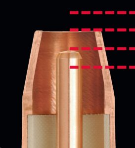
The ideal contact tip recess position varies according to the application. A general rule: As the current increases, the recess should also increase.
Use 100 percent CO2 shielding gas or a 75 percent CO2/25 percent argon mix in combination with a carbon steel solid wire. Aluminum welding wire requires argon shielding gas, while stainless steel wire works best with a tri-mix of helium, argon and CO2. Always reference the wire’s spec sheet for recommendations.
You can gauge heat input and travel speed by the weld bead produced and adjust accordingly to gain better control and better results. For example, if you produce a weld bead that is too tall and skinny, it indicates that the heat input is too low and/or your travel speed is too fast. A flat, wide bead suggests too high of heat input and/or too slow of travel speeds. Adjust your parameters and technique accordingly to achieve the ideal weld, which has a slight crown that just touches the metal around it.
These answers to frequently asked questions only touch on a few of the best practices for MIG welding. Always follow your welding procedures to gain optimal results. Also, many welding equipment and wire manufacturers have technical support numbers to contact with questions. They can serve as an excellent resource for you.PACKAGING CHANGE – Changes to Bernard Bag Packaging
PACKAGING CHANGE — Changes to Bernard Bag Packaging
Old Bernard Bags


New Bernard Bags


PACKAGING CHANGE – Changes to Tregaskiss Bag Packaging
PACKAGING CHANGES —
Changes to Tregaskiss Bag PackagingOld Tregaskiss Bags


New Tregaskiss Bags


Self-Shielded Flux-Cored Welding: Choosing Your Gun
Self-Shielded Flux-Cored Welding: Choosing Your Gun
Considering self-shielded flux-cored welding
Self-shielded flux-cored gun options
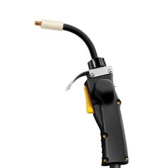
Proper maintenance, cleaning and technique
Optimizing self-shielded flux-cored welding
5 Common Failures in Robotic Welding and How to Prevent Them
5 Common Failures in Robotic Welding and How to Prevent Them
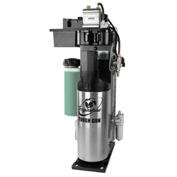
Failure No. 1: Burnback and contact tip wear
Failure No. 2: Broken cutter blades in the reamer
Other Causes for Broken Cutter Blades

Failure No. 3: Loss of tool center point
Failure No. 4: Broken discs

Failure No. 5: Incorrect tool path
Maintenance is key
DISCONTINUED PRODUCT – Tandem Robotic Torches
DISCONTINUED PRODUCTS –
Tandem Robotic MIG GunsTandem Robotic MIG Guns
Note: Availability and list prices of replacement parts for the affected products are subject to change without notice.DISCONTINUED PRODUCT – Service Parts for Quick-Change and Keyed Robotic Water-Cooled Guns
DISCONTINUED PRODUCTS –
Service Parts for Quick-Change and Keyed Robotic Water-Cooled MIG GunsService Parts for Discontinued Quick-Change Water-Cooled and Keyed Water-Cooled Robotic MIG Guns
Tregaskiss Expands Robotic MIG Welding Gun Offering
Tregaskiss Expands Robotic MIG Welding Gun Offering
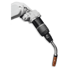
Anti-Spatter Sprayer: How to See the Best Results
Anti-Spatter Sprayer: How to See the Best Results
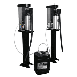
Follow these best practices for anti-spatter liquid usage
The spray containment unit also collects anti-spatter liquid runoff so it can be easily drained into a container and disposed of in accordance with federal, state and local environmental control regulations. Anti-spatter liquid cannot be reused.
Learn more about anti-spatter liquid and available accessories.
This article is the third in a three-part series focused on the use and benefits of anti-spatter liquid. Read article one, Spatter in Welding: Should You Consider Anti-Spatter Liquid? and article two, How to Select and Use Anti-Spatter Liquid.How to Select and Use Anti-Spatter Liquid
How to Select and Use Anti-Spatter Liquid
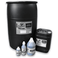
• Easy cleanup and no residue
• Compatibility with the nozzle cleaning station or reamer being usedSafety Tips
Consider these tips:Spatter in Welding: Should You Consider Anti-Spatter Liquid?
Spatter in Welding: Should You Consider Anti-Spatter Liquid?
What is anti-spatter liquid?
• Lowers cost for consumable inventory and management
• Reduces operating costs by improving weld quality and lowering reworkDoes my operation need to use anti-spatter liquid?
Save Money, Improve Performance with Bernard Replaceable MIG Gun Parts | Customer Testimonial
Save Money, Improve Performance with Bernard® Replaceable MIG Gun Parts
Bernard MIG Welding Consumables Save Time and Last Longer | Customer Testimonial
Bernard® MIG Welding Consumables Save Time and Last Longer
New HDP Contact Tips Provide Robotic Pulsed MIG Welding Benefits
New HDP Contact Tips Provide Robotic Pulsed MIG Welding Benefits
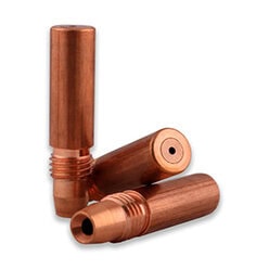
Demands of GMAW-P
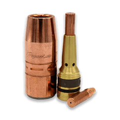
Contact tip advancements
Significant productivity gains
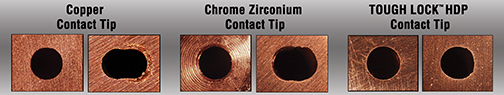
Additional benefits
Return on investment
Be sure to look at the big picture in terms of productivity and efficiency improvements for the entire operation.Improve productivity and efficiency


