7 Tips for Implementing a Robotic Welding Cell
Implementing robotic welding can significantly improve a manufacturing operation’s productivity and weld quality, but what are the robotic welding basics you should know to be successful? From choosing the right welding wire to establishing proper tool center point (TCP), many variables play a role in optimizing robotic welding cells to produce the best results.
Shaving even a few seconds from each weld cycle can save time and money. Minimizing the unplanned downtime for adjustments or repairs in the weld cell can also have a substantial impact on your bottom line.
Success with robotic welding requires a well-researched plan. The more planning done upfront, the less time and money you could spend later making fixes and process improvements.
Learning some basic tips for setting up a robotic weld cell can help to establish a repeatable and consistent process — so your operation can produce quality welds, reduce rework and maximize its investment.
Tip No. 1: Use proper weld settings
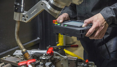
Proper weld settings for the application are based on factors including wire size and material thickness. Some welding power sources offer technology that allows welders to simply input the wire size and material thickness, and the machine will suggest recommended parameters for the application.
Without this technology, finding the correct parameters can involve a bit of trial and error. Sometimes the robot manufacturer, welding power source manufacturer or system integrator can assist in choosing and testing specific materials to provide a starting point for the proper welding parameters. Utilize the experience of these partners to help you arrive at the best starting point and be prepared for the future.
Tip No. 2: Choose the right wire
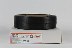
The choice of filler metal for a robotic welding system can significantly impact productivity, weld quality and the overall investment. Selecting the right wire for a robotic application is typically based on the material type and thickness, as well as the expected outcomes for the welded part. Welding equipment and filler metal manufacturers often offer charts to help you match a welding wire to your process needs.
While solid wire has been the industry standard in robotic welding for many years, metal-cored wire is an alternative that can offer productivity and quality improvements in some applications, particularly in the manufacture of heavy equipment and automotive exhaust, chassis and wheels. However, be aware that each wire type offers pros and cons for certain applications, so it’s important to research the type that is best suited to your application.
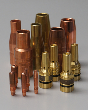
Tip No. 3: Consider the gun and consumables
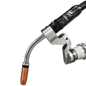
Robotic welding guns and consumables, including the nozzle, contact tip and gas diffuser, have a huge impact on performance in a robotic weld cell. The right combination can reduce unplanned downtime and improve overall efficiency of the cell.
Be sure the welding gun is rated with enough duty cycle and amperage for the application. To avoid excessive wear and premature failure, the gun should not rub against any part of the system or another robot in applications where multiple robots are being used on the same tooling.
Robotic welding systems typically operate at higher duty cycles than semi-automatic welding applications, and they may utilize transfer modes that are especially harsh on consumables. Consider using heavy-duty consumables that are more heat-resistant than standard-duty consumables. Chrome zirconium contact tips or tips specifically designed for pulsed welding processes are good options.
In addition, ensure all consumables are properly installed and tightened. Improper or loose connections produce more electrical resistance and heat that causes faster consumable wear with premature failures. Another common failure in robotic welding is improper liner installation. Always follow the manufacturer’s directions for liner installation and cut length. A liner that is cut too short can cause premature failures of other consumables in the system.
Tip No. 4: Reduce cable wear
Make sure there is good cable grounding in the weld cell to help prevent potential problems as the cell ages. There are two cables running from the welding power source; one is attached to the wire feeder and the other is grounded to the tooling. Often, these cables are long and run from the shop floor to an elevated platform or through wire trays. The section of cable running up the robot or running to a positioner will constantly move — causing greater wear over time.
Using a junction with high-flex ground cable at the base of the robot or the workpiece can save time and money in downtime and repair. With this solution, there is only a 6-foot section of cable to replace when it wears out, rather than replacing possibly 50 feet or more of ground cable that runs all the way back to the power source. However, keep in mind you should have as few breaks or junctions in the grounding cable as possible to maintain a better electrical connection.
When mounting a ground cable to the welding workpiece, it can be helpful to use copper anti-seize lubricant, sometimes referred to as copper slop. This supports the transfer of electrical current and helps prevent the mounting point from fusing together or deteriorating over time. The lubricant can be useful in all areas where there may be grounding current running through pins or any other semi-permanent contact points.
Proper cable management for the guns can also greatly extend cable life. The more any cable bends and flexes, the more wear and tear will occur — ultimately shortening cable life due to high heat and resistance. Work to minimize cable bending and flexing in your robotic process and tooling design.
Tip No. 5: Establish TCP
For repeatable and consistent weld quality, it’s critical to establish and maintain proper TCP. Welding operations can set their own standards for the acceptable amount of TCP drift, depending on the application and type of weld being made. When considering the tolerance of TCP variation, an acceptable starting point can be half the thickness of the wire diameter.
Many robotic systems today can use touch-sensing features to monitor TCP and determine how far it has moved from the original programmed settings. If a gun is determined to be out of the acceptable TCP range, the gun neck can be removed and recalibrated offline to factory specifications with a neck straightening fixture. Some systems also provide the capability to adjust TCP automatically with the robot. A third option is to leave the gun in place and adjust the robot teaching to accommodate the modified TCP. This is the most time-consuming solution and, therefore, often not acceptable for the manufacturing operation. It also requires the need to reprogram the robot if new factory specifications for TCP or a new neck are ever put into place — which is why this method is typically the last resort.
Set a schedule or standard for checking TCP, whether it’s every weld cycle, once a shift or even every time the torch goes through a reamer cycle. The length of time between checks is a matter of preference and weighing your priorities. It can be time-consuming to check every weld cycle, but this can save money in lost scrap and rework if a problem is found before welding occurs.
Tip No. 6: Program the robot path
The initial programming of the robot’s welding path can also involve much trial and error. When programming the path, consider the application, material type, welding process being used and gap size that must be filled. The weld quality and amount of spatter created are also impacted by the travel angle and whether it’s a pull or push weld. It can take time to dial in the correct path to achieve the desired quality.
After setting the home positions in the robotic program, it’s recommended to have the robot move to perch points or ready-to-enter points that are safely away from any potential collision points, so the system can move quickly with air cut moves to and from these points.
When programming the robot to move to a weld, it’s common to set the approach point just above the weld start location. Have the robot approach the start location at a slower and safer speed with the arc on. This approach position provides a good lead-in and typically won’t require adjustment unless the weld is relocated. Some robotic welding systems include technology that aids in setting the initial robot path.
The robot’s welding location can play a role in premature failure of the gun. If the robot is welding with a lot of flex in the gun at a tight angle, this can cause it to fail much faster. Minimizing robot axes five and six during welding can help extend gun life by reducing wear.
Tip No. 7: Ensure proper fit-up
Proper part fit-up in the upstream process is critical to consistent weld quality and robot path programming. Inconsistent fit-up or large gaps between the parts lead to weld quality issues such as burn-through, poor penetration, porosity and others — resulting in additional unplanned downtime to deal with these problems. Large gaps between the parts may also require double weld passes, adding to cycle times.
Closing
From wire and consumable selection to proper cable management and TCP, many variables play a role in weld quality and ultimately, the success of your robotic welding system. Careful planning at the start of the process and continued monitoring of these key factors helps optimize performance — so you can get the most from your robotic welding investment.