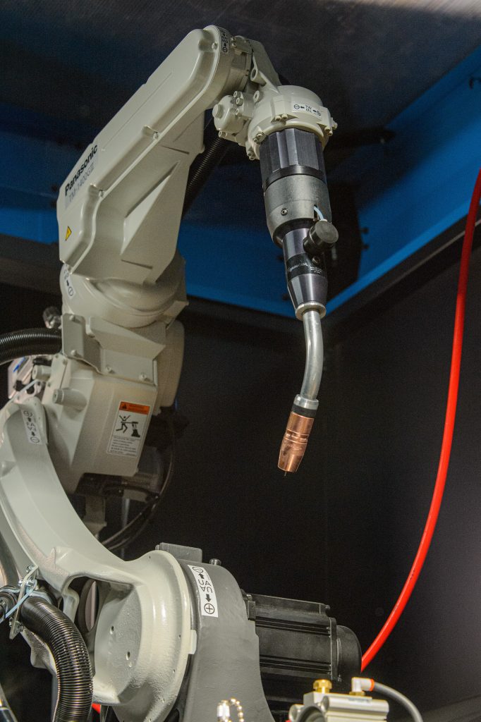
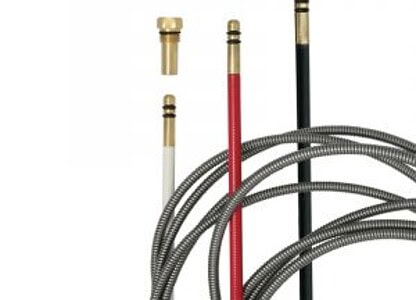
PRODUCT UPDATE — Material Improvement for Clean-Air® Fume Extraction MIG Gun Replaceable Hose Cover

You may have noticed a material improvement of the cable cover installed on all Bernard® Clean-Air™ fume extraction MIG guns. The new cable cover is more lightweight than the previous cover and allows greater flexibility of the hose assembly. Our replaceable cable cover hose protects from the damage that might be incurred on a hot workpiece, as well as extending the life of the hose for the Clean-Air fume MIG gun assembly.
For questions or more information, contact your local ITW sales representative.
PRODUCT UPDATE – Fume Extraction Neck Assembly Part Number Changes
PRODUCT UPDATE – Fume Extraction Neck Assembly Part Number Changes
Effective immediately, to simplify the ordering process on Bernard® Clean-Air® fume exhaust MIG guns, we have replaced the two parts needed to complete the complete the body assembly and vacuum tube assembly into one fume extraction neck assembly part number as shown in the chart below:
| Description | Fume Extraction Neck Assembly New Part Numbers | Discontinued Vacuum Tube Part Numbers and Body Assembly Part Numbers |
| 45° neck, medium — handle option T | 2390047 | 2390027 + 1040082 |
| 60° neck, medium — handle option T | 2390048 | 2390028 + 1040083 |
| 45° neck, medium — handle option N | 2390049 | 2390029 + 1040084 |
| 60° neck, medium — handle option N | 2390050 | 2390030 + 1040085 |
For questions or more information, contact your local ITW Representative
CONFIGURATOR SIMPLIFICATION: Changes to all automation gun configurators
CONFIGURATOR SIMPLIFICATION: Changes to all automation gun configurators
To continue delivering sustainable value to our customers, we regularly assess our product offering to ensure focus and opportunities to innovate our product portfolio.
Please be advised that, effective May 1, 2024, we are removing all TOUGH LOCK™ consumables and AutoLength pin options from our robotic, fixed automatic and cobot MIG gun configurators.
It is important to note the following:
- “AccuLock™ consumables” and “No consumables” will remain available options where currently available.
- TOUGH LOCK consumables are not being discontinued and can be ordered separately if required.
- No standard duty AccuLock consumable options will be available at this time. If standard duty consumables are required, be sure to configure the gun with the “No consumables” option and order the appropriate standard duty TOUGH LOCK consumables separately.
- Guns previously configured with TOUGH LOCK consumables and/or AutoLength pins will remain available for (re)order – no new TOUGH LOCK and/or AutoLength configurations will be available after May 1, 2024.
- AutoLength pins are not being discontinued and can be ordered separately if required.
Impacted configurators are listed below:
- TOUGH GUN TA3 ThruArm robotic air-cooled guns (TA1xxx)
- TOUGH GUN CA3 robotic air-cooled guns (RA1xxx)
- Tregaskiss 600 amp robotic water-cooled guns (RW16xxx)
- Tregaskiss MA1 fixed automatic air-cooled guns (MA16xxx)
- Tregaskiss MW1 fixed automatic water-cooled guns (MW1xxx)
- Tregaskiss BA1 cobot air-cooled guns (BA1xxx)
If you have further questions or would like more information, please contact your local ITW representative.
PRODUCT UPDATE — NEW ADDITION TO THE BERNARD FCAW SELF SHIELDED GUN PRODUCT OFFERING

PRODUCT UPDATE — NEW ADDITION TO THE BERNARD FCAW SELF-SHIELDED GUN PRODUCT OFFERING


We are proud to announce that effective immediately, a new 450-amp self-shielded FCAW series has been added to the Bernard self-shielded FCAW gun portfolio. The new IronPro™ self-shielded FCAW gun is ergonomically designed to provide excellent access and maneuverability in hard-to-reach weld joints and is ideal for rough use in harsh environments. The IronPro self-shielded FCAW guns also feature AccuLock™ S consumables to keep you welding in tight positions longer, with less contact tip changes and less troubleshooting.
Features and Benefits:
- Features AccuLock™ S consumables
- Choose from two neck sizes for different lengths and bend radii.
- Short handle better accommodates maneuverability for improved joint access.
- Sealed trigger keeps the trigger area slag and spatter free, reducing maintenance.
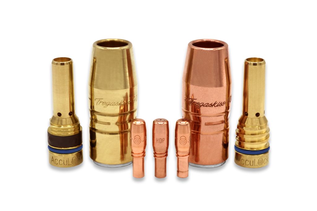
PRODUCT UPDATE — ACCULOCK™ S CONSUMABLES AND NEW NECK ON XS180 AND XS 260 TGX™ SERIES MIG GUNS
PRODUCT UPDATE — ACCULOCK™ S Consumables and New Neck on XS180 AND XS 260 TGX™ Series MIG Guns
We are pleased to announce that on March 1, 2024, we started offering XS180 and XS260 TGX (10’ and 15’) MIG guns with Bernard neck, silver color (part number 205-60) and AccuLock™ S consumables with Bernard® conventional liner.
DISCONTINUED PRODUCT – TGX Series MIG Gun Amperages
DISCONTINUED PRODUCT – TGX Series MIG Gun Amperages
To continue delivering sustainable value to our customers, we regularly assess our product offering to ensure focus on customer needs and opportunities to innovate our product portfolio. Accordingly, as of March 1, 2024, we have discontinued the XS300, XL300 and XL400 amp TGX air-cooled MIG guns. We are recommending our 200-amp Bernard BTB MIG guns to replace XS300, XL300 and XL400 amp TGX air-cooled MIG guns.
NOTE: We will continue to support all XS180 and XS260 TGX air-cooled MIG guns.
DISCONTINUED PRODUCT – Select Reamer Stand Heights
DISCONTINUED PRODUCT – Select Reamer Stand Heights
In effort to maximize efficiencies and continue to focus on delivering sustainable value to our customers, effective December 20, 2023, we will be discontinuing a variety of reamer stands due to low demand and sales volume.
| Part Number | Description |
|---|---|
| RST-20 | Reamer stand, 20-inch |
| RST-22 | Reamer stand, 22-inch |
| RST-23 | Reamer stand, 23-inch |
| RST-27 | Reamer stand, 27-inch |
| RST-29 | Reamer stand, 29-inch |
| RST-32 | Reamer stand, 32-inch |
| RST-35 | Reamer stand, 35-inch |
| RST-40 | Reamer stand, 40-inch |
| RST-45 | Reamer stand, 45-inch |
TOUGH GUN® reamer stands are still part of our product portfolio and will remain available, in heights between 18 and 36 inches in 6-inch increments.
PRODUCT UPDATE – Washers to Be Pre-installed on All Tregaskiss® Cutter Blades
PRODUCT UPDATE – Washers to Be Pre-installed on All Tregaskiss® Cutter Blades
As part of our ongoing commitment to continuous improvement, beginning in February 2024 customers will begin to notice that Tregaskiss® cutter blades are coming with a pre-installed washer which is secured and held in place by an o-ring. This incremental improvement provides more convenience for customers by ensuring the washer remains securely in place and gets properly re-assembled when the cutter blade needs to be removed or replaced.
Effective February 5, 2024, this modification will be rolled out as a running change across our complete lineup of cutter blades. There will be no change to cutter blade part numbers, but please note that packaging will change to accommodate the addition of the washer.

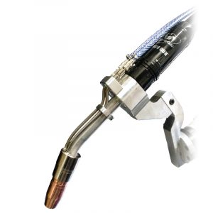
PRODUCT IMPROVEMENT – BA1 Cobot MIG Guns to Feature Lighter Unicables
PRODUCT IMPROVEMENT – BA1 Cobot MIG Guns to Feature Lighter Unicables
Effective February 20, 2024, as part of our ongoing commitment to continuous improvement, we are making a change to the unicable used on our Tregaskiss® BA1 cobot air-cooled MIG guns.
The new unicable better addresses customer needs for a lighter more flexible cable in their cobot welding applications. It is important to note the amperage rating of the BA1 cobot MIG gun will change from 385-amp to 350-amp with mixed gases at 100% duty cycle (ratings are based on tests that comply with IEC 60974-7 standards).
There will be no change to configured BA1 gun part numbers, but BA1 replaceable unicables are changing and will have the following new part numbers:
| Part Number | Description |
|---|---|
| BA1U03S | BA1 replaceable unicable, solid mount, 3 ft |
| BA1U03.5S | BA1 replaceable unicable, solid mount, 3.5 ft |
| BA1U04S | BA1 replaceable unicable, solid mount, 4 ft |
| BA1U04.5S | BA1 replaceable unicable, solid mount, 4.5 ft |
| BA1U05S | BA1 replaceable unicable, solid mount, 5 ft |
| BA1U05.5S | BA1 replaceable unicable, solid mount, 5.5 ft |
| BA1U06S | BA1 replaceable unicable, solid mount, 6 ft |
| BA1U07S | BA1 replaceable unicable, solid mount, 7 ft |
| BA1U08S | BA1 replaceable unicable, solid mount, 8 ft |
| BA1U09S | BA1 replaceable unicable, solid mount, 9 ft |
| BA1U10S | BA1 replaceable unicable, solid mount, 10 ft |
| BA1U12S | BA1 replaceable unicable, solid mount, 12 ft |
| BA1U15S | BA1 replaceable unicable, solid mount, 15 ft |
| EBA1U03S | BA1 replaceable unicable, solid mount (Euro), 3 ft |
| EBA1U03.5S | BA1 replaceable unicable, solid mount (Euro), 3.5 ft |
| EBA1U04S | BA1 replaceable unicable, solid mount (Euro), 4 ft |
| EBA1U04.5S | BA1 replaceable unicable, solid mount (Euro), 4.5 ft |
| EBA1U05S | BA1 replaceable unicable, solid mount (Euro), 5 ft |
| EBA1U05.5S | BA1 replaceable unicable, solid mount (Euro), 5.5 ft |
| EBA1U06S | BA1 replaceable unicable, solid mount (Euro), 6 ft |
| EBA1U07S | BA1 replaceable unicable, solid mount (Euro), 7 ft |
| EBA1U08S | BA1 replaceable unicable, solid mount (Euro), 8 ft |
| EBA1U09S | BA1 replaceable unicable, solid mount (Euro), 9 ft |
| EBA1U10S | BA1 replaceable unicable, solid mount (Euro), 10 ft |
| EBA1U12S | BA1 replaceable unicable, solid mount (Euro), 12 ft |
| EBA1U15S | BA1 replaceable unicable, solid mount (Euro), 15 ft |
If you have any questions regarding this change, please contact your local ITW sales representative.
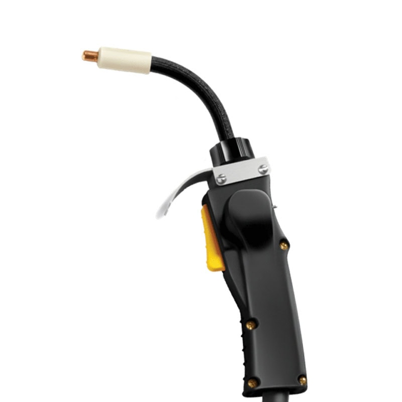
PRODUCT UPDATE — Change on Neck Body for all T and C Series Handle Configurations on Bernard BTB MIG Guns
PRODUCT UPDATE — Change on Neck Body for all T and C Series Handle Configurations on Bernard® BTB MIG Guns

Effective immediately, you will notice two differences on the neck body for all Bernard BTB MIG Guns with a T and C series handle configuration.
- The color of the neck body is changing from silver to black.
- Screw holes for the T and C series handle configuration have been added to the neck body.
This will be a running change as we deplete the current inventory of the old-style neck body. If you have questions, please contact your local ITW representative.
PRODUCT UPDATE — New Motor Lubricator Enhancements for TOUGH GUN® TT4A and TT4E Reamer Robotic Nozzle Cleaning Station
PRODUCT UPDATE — New Motor Lubricator Enhancements for TOUGH GUN® TT4A and TT4E Reamer Robotic Nozzle Cleaning Station
Improvements have been made to the dedicated motor lubricator on Tregaskiss® TOUGH GUN TT4A and TT4E reamers. Effective immediately, all new TOUGH GUN TT4 reamer orders will come equipped with the new lubricator, without any impact to the reamer part number. However, it is important to note that if ordering the lubricator separately, the part number has changed from TT4-LUB to TT4-2250.
New TT4-2250 motor lubricator enhancements:
- Better drip rate control provides more accurate and consistent oil feed rate into the motor
- No need to remove parts to check the oil level! Easily identify the oil level through a sight glass located on the outside of the lubricator
- Air fittings are metal which better protects them from spatter
Same mounting footprint, no special adaptors needed.
If you have any questions regarding this change, please contact your local ITW sales representative.
Five Equipment Adjustments to Improve Weld Quality
Five Equipment Adjustments to Improve Weld Quality
Regardless of your skill level, you need to make sure that the equipment you use, works as hard as you do. Consider these components of your welding system to help weld conistency. Could it be time to take a good look at your equipment? Read our article published in the November issue of Fabricating & Metalworking.
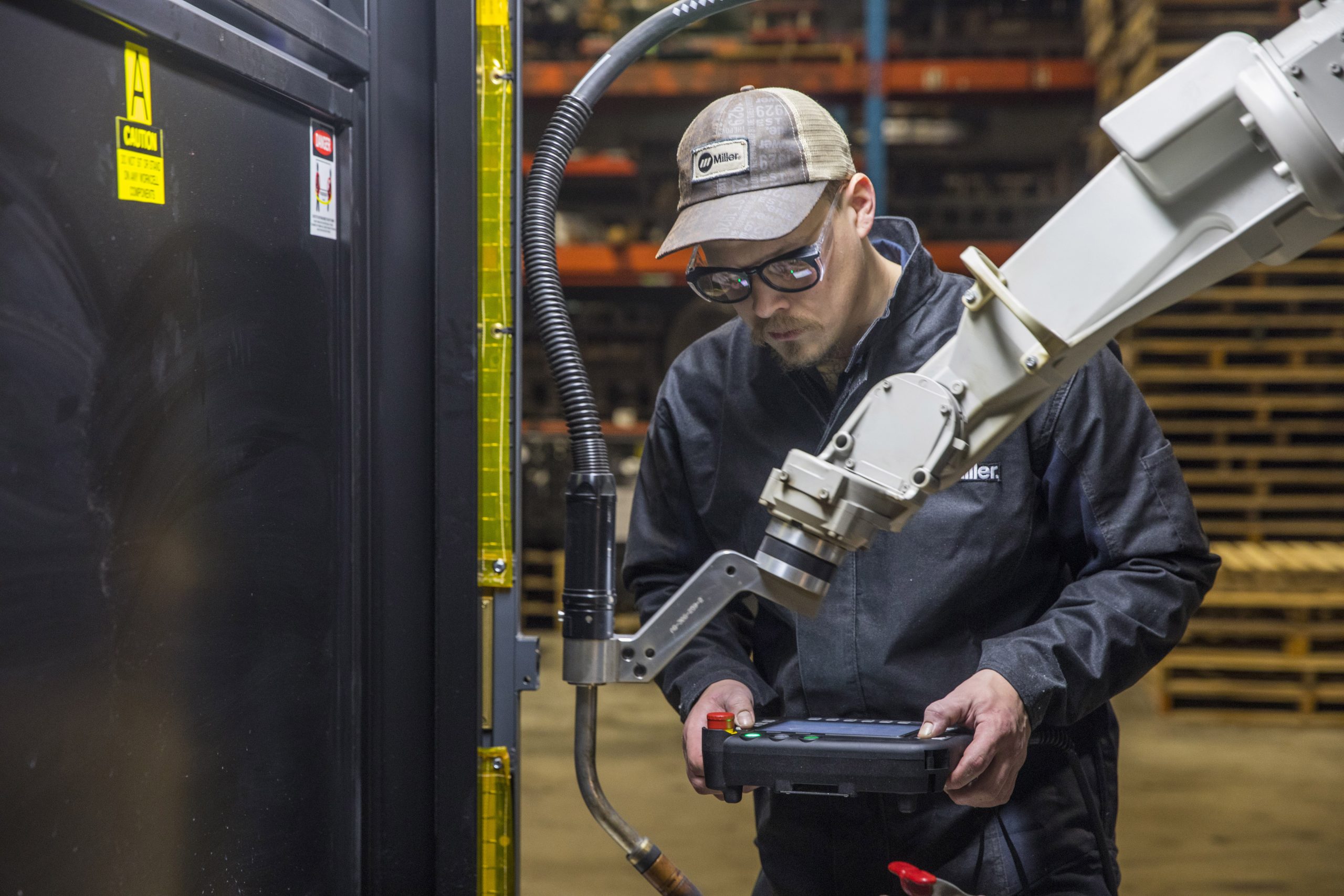
Choosing Between Robots and Cobots for Robotic Welding
Choosing Between Robots and Cobots for Robotic Welding

Learn how to recognize the key nuances between two welding-automation options, robots and cobots and how knowing these differences are essential to attain positive results. Have you ever wondered about the differences between robots and cobots? Learn more! “Choosing Between Robots and Cobots for Robotic Welding” in Metalforming Magazine
South Louisiana Community College Chooses Bernard® Semi-Automatic MIG Welding Guns and AccuLock™ Consumables for Welding Education | Customer Testimonial
South Louisiana Community College Chooses Bernard® Semi-Automatic MIG Welding Guns and AccuLock™ Consumables for Welding Education
South Louisiana Community College (SLCC) has made a game-changing decision to enhance its welding education program by incorporating Bernard semi-automatic welding guns and AccuLock consumables into its classrooms. This shift marks a significant departure from the MIG guns and consumables they had been using for decades.
The transition began within the last year after SLCC’s welding technology instructors began noticing some challenges the students were facing with the welding guns and consumables that they were using. They noticed it took students 20 minutes to change a liner with their current welding guns and consumables.
Enter Bernard. After meeting with the instructors and listening to their pains points and need for improvement – Bernard configured a lightweight MIG welding gun with the AccuLock S dual-locked liner consumable system to test in the classrooms. Instructors and students immediately saw the benefits.
The AccuLock S dual-locked liner system makes liner installation error-proof by eliminating the guesswork and potential errors that can occur when trimming a liner. More importantly, it maximized their limited time in the classroom. The superior performance of AccuLock contact tips stood out most. SLCC saw a remarkable 50% improvement in tip life compared to the products they were using previously. AccuLock contact tips lasted twice as long.
The school found the benefits of using Bernard’s MIG welding guns and AccuLock S consumables for instructional purposes were clearly evident. The lightweight and durable design, coupled with the extended consumable life delivered a substantial return on investment. Not only does the switch to Bernard provide cost savings, but it also equips inexperienced welders with the tools that can withstand the rigors of training and real-world applications.
Packaging Change — Wire Cutter No Longer Packaged Separately When Configured on a TOUGH GUN® TT4 Reamer
Packaging Change — Wire Cutter No Longer Packaged Separately When Configured on a TOUGH GUN® TT4 Reamer
October 23, 2023
In effort to consolidate and simplify packaging and shipments, please note that effective immediately, customers who order a TOUGH GUN TT4 reamer robotic nozzle cleaning station configured with a wire cutter will no longer receive their wire cutter in a separate package as part of their shipment. The wire cutter unit is now being included inside the same single box with the reamer.
Affected Part Numbers:
- All TOUGH GUN TT4 reamer part numbers ending in “WL” (i.e. TT4A093801WL)
- All TOUGH GUN TT4 reamer part numbers ending in “PL” (i.e. TT4E106001PL)
If you have any questions regarding this change, please contact your local ITW sales representative.
Discontinued Products — Select Bernard® and Tregaskiss® Consumables
Discontinued Products — Select Bernard® and Tregaskiss® Consumables
To continue delivering sustainable value to our customers, we regularly assess our product offering to ensure focus on customer needs and opportunities to innovate our product portfolio.
Accordingly, due to low demand, as of October 1, 2023, a complete list of discontinued products is now available. Click here to download the complete list in PDF format.
Understand the Truth About These 7 Robotic Welding Myths

Understand the Truth About These 7 Robotic Welding Myths
Estimated reading time: 7 minutes
Speed, accuracy, repeatability — welding automation boasts some big benefits. Using robots across a myriad of manufacturing applications has been a boon to the welding industry, but it hasn’t come without its fair share of misconceptions. Accepting those misconceptions could actually negate those big benefits — and no one has the time (or money) for that. Here are some common myths heard ’round the manufacturing floor — and where we land on them.
Myth 1: The more anti-spatter solution you use, the better the results
There seems to be a halo effect around the word “anti” — if it’s anti-“something,” it’s often assumed that the more you use, the better off you’ll be. In welding, that’s not necessarily the case. Using too much anti-spatter spray can actually cause more problems than it solves. When applying it to hot consumables, spraying just enough for it to dry on contact will create a sacrificial barrier that spatter won’t stick to as easily. If the solution is applied to the point where it’s dripping from the torch, it’s too much — and the excess spray will leak all over the parts and weld cell, leading to compromised weld quality, a messier weld cell and premature failure of the torch parts/consumables. Some operators will “dip” the consumables into a cup of the anti-spatter instead of spraying it, but this is also problematic because excess solution can cause the nozzle to become saturated and fail prematurely.
When welds are off location, there’s usually an underlying issue that’s causing the problem. Tip bore wear, variations in stamping batches or parts being misaligned due to tooling/spatter can all create a situation where welds are off location. Here, reassessing TCP can help determine what the root problem is rather than just blaming the torch and touching up points.
Apply only enough to get the job done. Tips to keep in mind when applying anti-spatter solution include:
- Position the nozzle at least 1 inch above the spray head
- Spray duration should be 0.5 seconds
- Adjust/reduce the spray frequency until the nozzle is perpetually wet
- The use of a spray containment unit allows the anti-spatter solution to be more effectively applied to the nozzle/consumables, while also keeping the weld cell cleaner by capturing over-spray
Myth 2: Using a contact tip that matches the size of the wire always leads to the best results
Contact tips can be the difference-maker between running an efficient welding process and accruing unwanted downtime. For smaller wire sizes in semi-automatic (or handheld) welding, using a contact tip that matches the size of the wire often leads to the desired results. However, in larger industrial operations where robotic welding is common, wire package size (vs. wire size) becomes more of the determining factor for selecting the proper tip size. Large-scale operations often use 1,000–2,000-pound drums or spools as the go-to options due to their high-volume output needs. The connection between the wire and the contact tip needs to be optimized for the tip to last as long as possible, which may require deviating from matching the tip and wire size.
Myth 3: The cheapest products will work
The adage goes, “You get what you pay for,” and that sentiment can definitely impact the quality of the work in welding. Investing in robotic welding equipment can add up quickly, so if there’s an opportunity to save a few bucks along the way, selecting a cheaper alternative seems like an appealing option. However, those savings often come at the expense of sacrificing product performance and weld quality, while creating more downtime. The issues experienced during the welding process will show in the end result, along with the bottom-line burn of frequent (and costly) consumable changeovers and excessive downtime for troubleshooting issues. Selecting high-quality, long-lasting consumables over cheaper alternatives will help reduce overall operating costs in the long run because it increases throughput while reducing inventory and downtime.
Myth 4: Changing the contact tip will always solve the problem
Well … not necessarily. If the contact tip fails and you replace it, you can consider the problem “solved” for at least a short time. However, if the tip keeps failing quickly, it’s safe to say that there’s a greater issue at play. Many factors can cause a tip to fail, including feeding or grounding issues. In those cases, if you put a new tip on, you’re inevitably just waiting until it fails again because you’re not addressing the root cause. If you’re going through tips at a high rate, this is the time to assess your operation and make sure that the drive roll tension is correct and/or the liner is trimmed properly. These are two common issues that can easily cause excessive “burn backs”/tip failure.
Myth 5: Higher drive roll tension results in better wire feeding
Choosing the right drive roll style and size for the wire being used is key to smooth and consistent wire feeding. However, if the tension is too high, or too low, it can diminish productivity, quality and efficiency. Tension that’s too tight can deform the wire, resulting in arc instability or burn backs (and too little tension can cause the wire to slip). If the system constantly needs more tension to push wire through, it likely means something else within the system is failing. For example, debris buildup in the liner can inhibit the right tension setting from being effective. To help mitigate the need to crank up the tension, make sure it is set correctly each time the wire spool/drum is changed. Additionally, be sure that the inlet guides are clear/not worn and clean the drive roll surfaces with a wire brush periodically to help maintain proper wire feeding.
Myth 6: Increased gas flow results in less porosity
This is another instance where the idea of “more is better” can be misleading. You definitely need enough gas to cover the weld pool, but turning up the gas doesn’t necessarily result in less porosity — in fact, it could create turbulence and MORE porosity. Proper gas coverage is based on flow, not pressure. If a system isn’t set up properly and the nozzle gets blocked with too much spatter/debris, there won’t be sufficient gas volume (flow) to protect the pool.
Leaks in the gas system or excess air flow within the weld cell can also impact the coverage of the weld pool, regardless of how high the gas flow rate is set. Instead of just defaulting to increasing the flow, do a quick run-through of the robotic system to verify that there is a proper tip-to-work distance and that the rest of the system is configured and running correctly.
Myth 7: Off-location welds are always the gun’s fault
In many applications, weld locations are extremely important. Even though the robot is physically going where it’s programmed to go, if the wire isn’t placed in the joint properly, it could be detrimental to the end product.
When welds are off location, there’s usually an underlying issue that’s causing the problem. Tip bore wear, variations in stamping batches or parts being misaligned due to tooling/spatter can all create a situation where welds are off location. Here, reassessing TCP can help determine what the root problem is rather than just blaming the torch and touching up points.
Avoiding these common missteps in robotic welding will help you maximize uptime and throughput while minimizing costs — a win from start to finish.
Written by Ryan Lizotte (ryan.lizotte@tregaskiss.com), Technical Services Manager, Tregaskiss.
Republished with permission from Fabricating and Metalworking, (October 2023)
PRODUCT UPDATE – CHANGES TO THE TREGASKISS® 600 AMP ROBOTIC WATER-COOLED MIG GUN OFFERING
PRODUCT UPDATE – CHANGES TO THE TREGASKISS® 600 AMP ROBOTIC WATER-COOLED MIG GUN OFFERING
September 20, 2023
In order to ensure focus on opportunities to innovate our product portfolio and continue delivering sustainable value to our customers, the changes identified below will be made to the Tregaskiss® 600 amp robotic water-cooled MIG gun offering effective September 29, 2023.
Physical changes to the product:
The gun housing of 600 amp robotic water-cooled MIG guns not equipped with wire brake will feature a wire brake plug (part number RW16-WBP). This change will also allow customers to install wire brake at a later date with the appropriate wire brake kit without having to change the gun housing.
There will be no change to MIG guns equipped with wire brake.
Changes to configurable options:
Additionally, due to low demand, please note that all 45-degree neck and 0.035” (0.9 mm) wire size options will be removed from the 600 amp robotic water-cooled MIG gun configurator.
If you have questions or need assistance with regard to these changes, please contact your local ITW welding sales representative.
Self-Shielded Gun Performance

Self-Shielded Gun Performance
Estimated reading time: 5 minutes
Self-shielded flux-cored welding is frequently used for structural construction and other jobsite welding since it offers a significant productivity advantage compared to stick welding.
Welders using this process are likely holding their welding guns for much of the day, and they may be standing on elevated girders or lifts trying to get into tight places to complete a weld. Because of this, it’s important to choose a self-shielded flux-cored gun that is comfortable, lightweight and maneuverable to help get work done efficiently.
Here are several key factors to consider when selecting a self-shielded flux-cored welding gun and tips for properly maintaining it to optimize performance.
1. Flux-Cored Gun Options
Not every welding gun fits every application. They come in various amperages and configurations, with features that include heat shields, configurable necks and adjustable cable lengths. The key is finding a flux-cored gun that works for each welder, since many options come down to operator preference.
2. Amperage
Guns rated at 350 or 450 amps are common in structural field welding applications. Guns rated at 600 amps are also available but used less often due to being heavier. It’s important to avoid undersizing the welding gun since it can lead to overheating and other problems.
When selecting the gun amperage, consider the wire sizes that will be used most often. Typical wire sizes for a 350-amp gun are 1/16 inch and smaller. Wire sizes for 450-amp guns are 0.72 inch and larger, including 5/64 and 3/32 inch.
3. Replaceable or Fixed Cable Liners
Some self-shielded flux-cored guns are available with either a replaceable cable liner or a fixed cable liner. The demanding environments where self-shielded flux-cored welding takes place can be hard on the gun and consumables, so replaceable liners provide benefits. They offer quick and easy cable maintenance and can extend product life, since welders can change out components that have high levels of wear. Guns with replaceable liners also tend to have a lighter weight cable and provide more flexibility to weld around edges or corners.
Guns with fixed cable liners are often larger, which can be an issue when welding in tight spaces. The cables are also typically stiffer and more rigid, so they can take more abuse. Once a fixed cable liner has reached the end of its useful life, the entire gun must be replaced.
4. Necks
Gun necks are available in varying lengths and bend angles. The choice for the application often comes down to operator preference or weld joint access and configuration.
A slimmer neck provides a better view of the weld pool and improved access to tight areas. A shorter neck typically provides more control compared to a longer neck. Still, operators may prefer a longer neck to increase the distance between themselves and the heat of the weld puddle — especially in higher amperage applications.
Keep in mind that lightweight, rotatable necks help reduce operator fatigue by aiding with posture and positioning, and they improve weld visibility.
5. Trigger
In the field, triggers that get wet or covered in dirt still need to work, so it’s important to purchase a quality gun that includes a durable trigger. Look for a gun with an enclosed trigger. This protects the contacts inside a housing, so the trigger is less prone to wear and breakage. If you’re using a replaceable cable liner, it may have an internal or external trigger lead. Be aware that external trigger leads may require more maintenance because they can easily get snagged or catch on things like bolt heads. However, they are typically quick and easy to replace.
6. Handle
A handle needs to be rugged and durable for the jobsite, but it should also feel comfortable in the operator’s hand.
A self-shielded flux-cored gun with an optional dual schedule switch allows for wire speed adjustment while welding. In some guns, this switch is integrated into the handle to keep it protected from spatter. The ability to toggle between weld parameters easily—without having to stop welding and change settings—saves time and improves productivity.
The Best Results
Beyond choosing the right gun for the job, it’s also important to use and maintain it properly. Consider these tips for optimizing gun performance.
Store and handle it properly: Jobsites can be dusty, dirty places. Be sure to store guns and cables properly when not in use. Roll the cables up and put the gun away in a clean, dry place so there’s less risk it will be damaged.
Maintain it as needed: Keep the gun and all components clean and check all connections periodically. Loose connections can cause electrical resistance and heat buildup, which can result in premature wear. Take the time to regularly blow out the liner with clean, compressed air to remove dirt and debris. Immediately address any damage to the gun components with maintenance or replacement.
Invest in quality consumables: Consumable choice often comes down to cost or operator preference. However, investing in high-quality consumables can help extend the life of the gun, provide better performance and reduce downtime for changeover.
Closing Thoughts
The self-shielded flux-cored process can deliver significant benefits for productivity and efficiency. Choosing the right gun and components—and maintaining them properly—plays a key role in optimizing your results.
Written by Stephen Bennett (stephen.bennett@bernardwelds.com), Mechanical Engineer, Bernard, Republished with permission from Modern Contractor Solutions (August, 2023)
PRODUCT UPDATE – 350 AMP MA1 FIXED AUTOMATIC MIG GUNS TO BE REPLACED WITH 385 AMP MA1 MODELS

PRODUCT UPDATE – 350 AMP MA1 FIXED AUTOMATIC MIG GUNS TO BE REPLACED WITH 385 AMP MA1 MODELS
September 5, 2023
Effective September 29, 2023, the 350 amp MA1 fixed automatic MIG gun will be removed from the Tregaskiss product portfolio and will be replaced with the existing equivalent 385 amp MA1 fixed automatic model. This initiative allows us to focus on delivering our best quality solution to our customers.
The only differences between the 350 amp and the 385 amp models are as follows:
- The outside diameter of the 385-amp cable is 0.1” larger than the 350-amp cable
- The length of the rear spring strain relief on the 385-amp model is 4.64” shorter than on the 350-amp model
- The outside diameter of the rear spring strain relief on the 385-amp model is 0.19” larger than on the 350-amp model
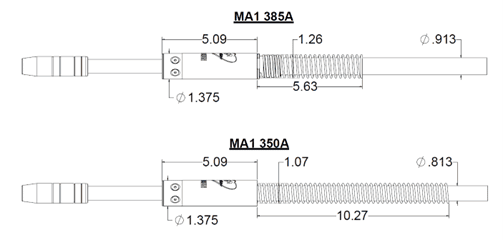
Affected Part Numbers:
- All fixed automatic MIG gun part numbers beginning with MA15
Replacement Gun Options:
- The 385 amp model is available as a direct replacement by simply changing the “MA15” prefix in your configured gun part number to “MA16”
If you have any questions or need assistance with regard to these changes, please contact your local ITW sales representative.
Best Practices For Weld Cell Layout

Best Practices For Weld Cell Layout
Today, even the smallest weld shops are making the jump to robotics, and even the largest, highly automated OEMs likely have semiautomatic weld cells for repairs or for welding parts that don’t lend themselves to automation. In automotive manufacturing, these manual cells may be midway through the line for welding frames or at the end for minor rework. If you’re in heavy equipment manufacturing, you might automate multipass welding on thick parts and reserve semiautomatic welding for tacking the parts or adding specialized components.
No matter your industry or your level of welding automation, an effective weld cell layout can help. Work needs to flow in an orderly fashion. Power, grounding, and wire feed cables need to be properly managed. And, of course, you need to ensure welders can work safely, consistently, and with good ergonomics. Proper layout supports high productivity and quality, along with cost savings.
The Big Picture
Whether robotic or semiautomatic, a well-designed weld cell makes efficient use of available space, where every component—the power source, welding gun, weld table, cables—ensures parts can be produced with little interruption. Streamlining workflow is a good first step. This involves setting up equipment in a way that helps operators avoid handling parts multiple times. Double handling of parts adds non-value-added seconds to the overall manufacturing cycle time and reduces the capacity for completed parts sent out the door. Think with an assembly line mentality.
Look beyond the weld cell to how parts are being delivered. For example, when an operation requires that parts receive semiautomatic tack welds before robotic welding, work must flow at a consistent pace to prevent the welding robot from sitting idle. To ensure a steady supply of parts and prevent bottlenecks, the cell should have a single point of entry. For optimal workflow, parts should move out of the weld cell in the same direction.
Minimize the distance a part needs to travel by keeping assembly points close together. Weld cells contributing to the completion of a single weld assembly should be in the same area of the facility. This proximity not only reduces time for moving a part, but it also lessens the number of footsteps operators need to make. Excessive movement in a welding cell is considered non-value-added work.
If you notice bottlenecks or operators or welding robots standing idle, or operators walking too far between weld cells, you might consider performing an audit. Any idle operation results in a failure to capitalize on the investment of that process. An audit can help you identify the causes behind these problems and implement solutions. The aim is to balance out the operations so that every aspect contributes to value-added work and high productivity.
The Semi-Automatic Weld Cell
Welding ergonomics are at the center of a semiautomatic welding cell layout. A more comfortable, healthier welding operator is a more productive one. Setting up the weld cell in a way that minimizes the need to reach repetitively or move awkwardly can reduce the risk of work-related musculoskeletal disorders.
Try to position the workbench or workpiece between the welding operator’s waist and shoulders, since this promotes a neutral posture that reduces stress on the body. When welding large components, use positioners or weld tables that move or rotate the part to the correct height and angle.
The same holds true when providing operators with a MIG gun that suits them, whether it be a curved or straight handle. Locking triggers help support comfort, as do rubber mats to stand on.
Strategically locating the power source and wire feeder can make the cell more efficient. Keep the two pieces of equipment as close as possible, so the operator can easily access them. Close proximity allows for shorter power cables for smoother wire feeding and also reduces electrical resistance drops so welding parameters remain more consistent.
Keep ground cable connections to a minimum. Some companies string together welding cables between weld cells for the same power source. This practice is inefficient, however, and can lead to problems. The multiple junctions can wear out easily, which causes electrical resistance and poor weld quality over time. The electrical resistance also can shorten consumable life, resulting in erratic arcs and burnbacks, leading to more downtime for contact tip changeovers.
The Robotic Weld Cell Layout
Implementing an effective robotic welding cell layout requires careful planning and attention to detail. One of the best approaches is to test the layout through virtual modeling or 3D simulation. These software programs can simulate the welding gun configuration—neck length, nozzle, and mounting (solid versus clutch)—to ensure it will operate properly within the work envelope. They also consider weld sequencing, robot arm movement, fixturing, and the parts to be welded so that you can be confident everything will work as planned.
Take the time to simulate the weld cell layout and process before equipment integration to avoid issues once the welding robot is in service. Simulations help prevent downtime during mass production for troubleshooting and potential expenses for revamping tooling or replacing components.
They also can model another key factor—welding robot reach. Be sure to match the size of the part with the reach of the robot. The robot must be able to reach all weld joints on the part; otherwise, you might need multiple robots for the application. A single, small welding robot won’t suffice for welding on a large part. If you have a weld on the edge of the reach envelope, you might not be able to achieve the optimal welding gun angle to create quality welds. This can add costs for rework, and you’ll likely need to replace stretched power cables that fail prematurely.
Regarding tooling, you might be tempted to purchase less expensive options—though such tooling might not have the features you need, such as the appropriate number of clamps or location pins. This can lead to inconsistent part fit-up or locating that requires multiple passes to fill the weld joint, adding to cycle time. You might experience more downtime as you reprogram the welding robot to accommodate the gaps, or you may end up needing to invest in touch sensing to locate the joint. Even worse, you might need to upgrade your tooling after the initial design phase—a costly step.
Also consider the positioners. Their size and weight capacity must account for both the weight of the part and the tooling. Design the robotic cell for the heaviest part to be welded.
Where you place the power source and wire feeder matters as they both impact power cable management and grounding. If space is at a premium, you may want to place the welding power source above the robot cell on a mezzanine. This way, you can run the power cable and ground leads down channels in the cell’s back wall directly to the tooling and welding robot.
These leads are stationary—except for the ones on the robot, so be sure to account for the robot’s air movements to minimize wear on the cables. Placing a junction power block at the base of the robot and running a high-flex power cable from that base up to the wire feeder can help save time in repairs, and it can save money. If the high-flex cable becomes worn, you just replace that shorter piece instead of the entire cable. The same approach works for the grounding leads.
Finally, determine the best location for the nozzle cleaning station or reamer. This peripheral cleans the nozzle of spatter during routine pauses in welding. It helps extend consumable life and reduces downtime for changeover.
The reamer needs to be close enough for the robotic welding gun to engage fully for the ream cycle. If you’re operating two robots close together, you can program them both to use the same reamer. Avoid mounting the reamer anywhere but a flat surface, since positioning it at an angle can cause anti-spatter to leak over equipment or fixtures.
Avoid interrupting the weld cycle by cleaning the nozzle during robot idle time. For example, consider cleaning the nozzles while parts are being transferred in and out of the fixture or while components are being loaded into a weld cell.
Small Moves, Big Impact
If you’re experiencing bottlenecks or missing productivity or quality goals, take a look at the welding cell layout. In a semiautomatic setup, never overlook welder comfort and safety. In a robot cell, moving power cables, power sources, wire feeders, or anything else can change how much that cell can produce over a shift.
The little things matter, and missing just one detail can snowball into bigger problems down the road. Small changes can make a big impact on the efficiency you can achieve.
Written by Justin Craft (justin.craft@bernardwelds.com), Field Technical Services Specialist, Tregaskiss and Bernard, Republished with permission from The Fabricator (August, 2023).
Proper Robotic Welding Gun Configuration

Proper Robotic Welding Gun Configuration
Estimated reading time: 6 minutes
The welding gun is a vital piece of equipment in a robotic welding system, serving as the conduit for the welding wire, gas, and power. However, it can sometimes be an afterthought when companies implement an automated welding solution. Unfortunately, this oversight can lead to a host of problems, not to mention frustration. That is especially true for first-time users making the investment.

The wrong robotic welding gun can also cause issues for those more experienced with robotic systems. It’s not uncommon for companies to purchase the same gun for a new robot and tooling when, in fact, it may not be the best option.
Companies also need to determine their welding amperage and arc-on requirements for the application. This ensures that they purchase a robotic welding gun with the proper duty cycle — the amount of welding that can occur at a rated output over a period without causing damage to the gun.
Robotic welding guns are available in a variety of ratings, including air-cooled models that operate at 350 or 385 A at 100% duty cycle.
Today, most robotic welding systems are through-arm models in which the power cable runs through the casting of the robot arm. As a first step in configuring a robotic welding gun for these systems, it’s important to know the make and model of the robot, power source, and wire feeder. Each equipment manufacturer has a different interface that dictates how each piece of equipment connects with one another.
There are higher amperage water-cooled options, which are typically 400 A and above, available in the marketplace. Some of these may be rated at 100% duty cycle, while others are rated at 60%. Don’t be fooled by high amperage unless it’s at 100% duty cycle.
Hybrid options are available for companies that want the simpler construction of an air-cooled robotic welding gun with the added cooling capacity of a water-cooled one. These guns have external water lines that circulate water around the nozzle to keep the front-end consumables cooler.
For a robotic welding gun to access the weld joints, it’s critical that the work envelope is adequate. Companies need to consider not just the size of the gun but also the space that is available when the tooling, fixtures, and parts are all in place. Joint design and weld sequencing also factor into the equation. It’s important that there is room and time for the welding gun to weld the joints in a sequence that keeps heat to a minimum. Companies should avoid heat soaking the parts, so they don’t become distorted.
A robot integrator can conduct a 3D simulation using models provided by the robotic welding gun manufacturer through computer-aided design (CAD) to make sure the gun and neck have the proper access and reach within the given space. The CAD model can also show whether the selected gun has the correct tool center point (TCP) and can extend to the nozzle cleaning station for reaming or to a service window for consumable changeover. A service window supports safety in the operation by eliminating the need for an employee to physically enter the cell.
Configuring the Gun
Some robotic welding gun manufacturers offer online configurators that allow companies to customize the equipment for their exact application. These configurators guide the user through a step-by-step process, providing options to choose from for each component. With or without this tool, companies need to consider what their needs are based on their upfront assessment.
Gun mount: There are two mounting options for a robotic welding gun to protect it in the event of a collision — a solid arm mount and a clutch. If the robot or end user’s safety procedure requires external collision detection, a clutch can be added to the system. This component functions both mechanically and electrically by recognizing a collision and sending a message to the robot controller to stop the system. If procedures allow for reliance on only the robot’s collision detection, then a solid mount will suffice.
Neck: The neck length and angle must provide the approach angle to weld parts properly and to allow for smooth wire feeding. Standard neck angles are 22, 45, and 180 deg. Through-arm robots generally use a 45-deg neck; however, that should be verified with the CAD model/simulation before implementing. Companies will also need to take into consideration the welding wire they are using. For example, aluminum wire requires a straighter neck to feed through properly since it is so soft.
Welding cable: For through-arm robots, the make and model dictate the cable length. For conventional robots (where the cable assembly runs outside the robot arm), the gun cable length also depends on the robot make and model along with the location of the feeder. It may be remotely mounted or mounted on the robot itself. There is more flexibility with cable length for these robots, but it’s important not to use too long of a cable since this can lead to wire-feeding issues. Conversely, a cable that is too short can stretch and break down quickly.
Welding consumables: When choosing contact tips for the robotic welding gun, look at the welding process. Pulsed gas metal arc welding (GMAW-P), for example, is quite hard on contact tips due to its high-frequency waveforms. This process requires a harder tip or a contact tip specifically designed for pulsed welding.
The chosen nozzle needs to allow proper access to the weld joint. A tapered nozzle works well when using smaller-diameter wire and contact tips. Higher-premium consumables are a good choice since these last longer and reduce downtime and labor for changeover.
Welding supervisors and operators should schedule time to perform preventive maintenance, such as checking connections and visually inspecting consumables for spatter, during routine pauses in welding.
Liners are another factor to consider, and the welding wire being used affects the choice. Flux- and metal-cored wires tend to be stiffer and harder to feed than solid wires. They require an extra-heavy-duty liner to support the wire and gain smooth feedability as it moves toward the contact tip. A D-wound galvanized wire works well. Companies can also use this liner for solid wire with good success.
Maintaining Efficiency
Companies invest in robotic welding systems to increase quality, productivity, and cost savings through a fast, repeatable process. To gain those benefits, every part of the system needs to be functioning optimally. Ensuring that the robotic welding gun has been configured properly before implementing the system can prevent downtime and extra expenses.
This article was written by Ryan Lizotte (project manager, Tregaskiss, Windsor, Ontario, Canada) for the American Welding Society.
MIG Welding FAQ: Best Practices for MIG Success

MIG Welding FAQ: Best Practices for MIG Success
Estimated reading time: 6 minutes
MIG is the most frequently used welding process in general manufacturing and fabrication, thanks to its ease of use, versatility, and productivity benefits.
While MIG is widely used, some operations may still run into issues that require troubleshooting. Understanding the basics of MIG welding and following best practices for operator technique as well as gas and consumable selection can help optimize results with the process.
Q: What are the main advantages of MIG welding?
MIG offers productivity benefits when compared to some other welding processes such as TIG and Stick, thanks to its higher travel speeds and deposition rates. MIG is also considered easier for new welders to learn, so it can be a good option for operations that struggle to find skilled welders.
MIG could be utilized with either solid filler wires or tubular wires such as Metal Cored and when used with Flux Cored wires it is referred to as Flux Cored welding. Tubular wires in general can be run at higher speeds and deposit more weld metal, so they even offer higher productivity gains than Solid wires.
Q: What are the differences between MIG and TIG welding?
There are many factors to consider when choosing the right welding process for your application. These include base material type and thickness, weld appearance requirements, productivity requirements, the welding environment and available skilled labor.
TIG welding is generally used in niche applications, such as those that require high-precision welds or extremely high aesthetic quality. TIG is frequently used with special-grade materials like titanium or stainless steel. In comparison, MIG can be used in higher production applications where increased throughput is important, and it’s a good option for a wide variety of metals.
A typical travel speed in TIG welding is 4-6 inches per minute. With MIG welding, travel speeds are much higher; 6 inches per minute are considered slow, and 15 to 20 inches per minute are common. Deposition rates are also much higher with MIG welding.
Regarding training, TIG is considered the most difficult welding process to learn and master since it uses both hands. An operator may take a few months to become proficient in TIG, while a new welder could be proficient in MIG within a week or two.
Q: What is the right shielding gas for MIG welding?
Shielding gas plays an important role in determining weld penetration profiles, arc stability, mechanical properties of the finished weld, the transfer process you use and more.
The filler metal manufacturer often provides shielding gas recommendations for the type of wire being used, so it’s a good idea to first consult the wire specification sheet.
When using flux-cored wire, 100% CO2 or an 80/20 Argon/CO2 mix are common choices. When it comes to solid wire or metal-cored wire, the right gas is dependent on the transfer mode being used. A short-circuit transfer mode works with 100% CO2 gas in most cases but can still run on mixed gas. While using a pulse or spray transfer, a higher Argon content is needed, and an 80/20 Argon/CO2 is the right choice.
The base material also plays a role in choosing the right gas. Aluminum requires 100% argon, while stainless steel requires at least 98% argon.
Q: Which is better: a push or a pull technique?
The technique choice may come down to operator preference in most cases, but there are some best practices. For example, when welding aluminum, a push angle is generally better because it helps the cleaning action of the oxidation layer on aluminum, similarly uphill position, a push angle is good for visibility and penetration. While if you use Flux Cored wire to weld carbon steel then a pull angle is going to work better in this case to give enough time to the slag not to be entrapped in the weld metal.
Q: What is the proper wire stick-out?
Maintaining a proper stick-out is important to achieving the best results in MIG welding, a too-long or a too-short stick-out will affect the weld quality and appearance. A 3/8-inch stick-out is a good starting point, but operators can deviate from that based on preference, wire diameter and accessibility to the weld.
Q: What amperage MIG welding gun is needed?
To choose the right MIG welding gun, consider the specifics of the application. The wire feed speed and wire diameter are two of the most important factors in determining proper gun amperage. Are you welding heavy wall materials, like heavy equipment or heavy steel structures? Those jobs will likely require a high deposition, hence a high-amperage welding gun — such as an Air-cooled 400-amp gun with at least a 60%-80% duty cycle or above, and in some cases a water-cooled gun. If you weld lighter walls and shorter beads, you may consider a 200 to 300-amp gun.
The most common amperage choice in the industry is a 300- to 400-amp, air-cooled MIG gun. This gun can address the majority of the MIG welding applications and can run the most common wire sizes such as 0.045” and 0.052”.
A good starting point would also be the welding procedure in place that specifies the amperage needed for the weld, which would help in choosing the gun’s amperage. Another easy way is to match the welding machine amperage output, a 400-amp welder would run well with a 400-amp gun in most cases, but this might not be the most effective way to select the right amperage gun when compared to the other methods mentioned above.
Q: How can an operation make consumables last longer?
Using the OEM consumables designed to be used with a specific MIG gun and welding system is important. Because these consumables are machined to very tight tolerances and go through high-quality measures which in turn is translated into higher quality welds and longer consumable life.
Be sure to choose a contact tip that is the appropriate size for the wire diameter — an oversized or undersized contact tip will wear faster and result in poor performance. In addition, follow the gun manufacturer’s recommendations for consumable installation and changeover, check connections regularly, install and trim to the right length, select the right nozzle material, size and recess/extension, and finally clean your consumables regularly and change them when needed.
Written by Mostafa Hanafy (mostafa.hanafy@tregaskiss.com) , Market Segment Manager, Tregaskiss and Bernard. Republished with permission from Fabricating and Metalworking (August 2023).
NEW PRODUCT — ACCULOCK™ S FOR CONVENTIONAL LINER STARTER KIT — NOW AVAILABLE

NEW PRODUCT — ACCULOCK S FOR CONVENTIONAL LINER STARTER KIT — NOW AVAILABLE
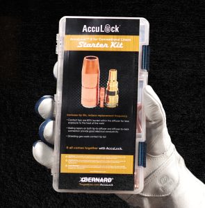
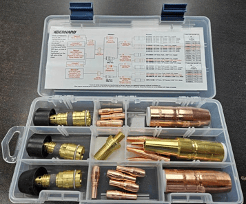
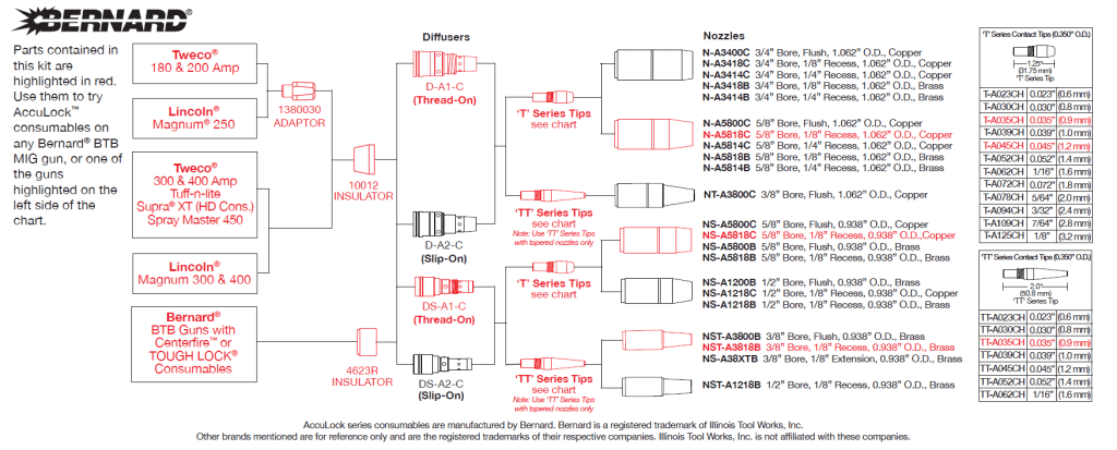
The AccuLock™ S for Conventional Liners starter kit (part number: ALCSK-1) is designed to help welders convert from their current BTB MIG gun consumables to AccuLock™ S consumables.
The kit contains everything needed for welders to swap their current nozzle, diffuser and contact tip with AccuLock™ S consumables with the ability to still use their existing conventional liner. Contact your distributor for more information or to order a kit today!