Ways to Save More Money With a Robotic Welding System

More and more welding operations are investing in robotic welding systems to gain a competitive edge. Such systems not only deliver fine-tuned programming to ensure the accuracy, speed and repeatability needed for generating high-quality welds, they also further productivity and efficiency for an operation. Along with the productivity gains and quality improvements, saving money is a key reason companies are choosing to implement them. Here are seven ways companies can increase cost savings and ROI — beyond the benefits of the robotic welding system itself.
Read the full article featured in Fabricating & Metalworking Magazine.
Choosing Between Robots and Cobots for Robotic Welding
Choosing Between Robots and Cobots for Robotic Welding

Learn how to recognize the key nuances between two welding-automation options, robots and cobots and how knowing these differences are essential to attain positive results. Have you ever wondered about the differences between robots and cobots? Learn more! “Choosing Between Robots and Cobots for Robotic Welding” in Metalforming Magazine
Understand the Truth About These 7 Robotic Welding Myths

Understand the Truth About These 7 Robotic Welding Myths
Estimated reading time: 7 minutes
Speed, accuracy, repeatability — welding automation boasts some big benefits. Using robots across a myriad of manufacturing applications has been a boon to the welding industry, but it hasn’t come without its fair share of misconceptions. Accepting those misconceptions could actually negate those big benefits — and no one has the time (or money) for that. Here are some common myths heard ’round the manufacturing floor — and where we land on them.
Myth 1: The more anti-spatter solution you use, the better the results
There seems to be a halo effect around the word “anti” — if it’s anti-“something,” it’s often assumed that the more you use, the better off you’ll be. In welding, that’s not necessarily the case. Using too much anti-spatter spray can actually cause more problems than it solves. When applying it to hot consumables, spraying just enough for it to dry on contact will create a sacrificial barrier that spatter won’t stick to as easily. If the solution is applied to the point where it’s dripping from the torch, it’s too much — and the excess spray will leak all over the parts and weld cell, leading to compromised weld quality, a messier weld cell and premature failure of the torch parts/consumables. Some operators will “dip” the consumables into a cup of the anti-spatter instead of spraying it, but this is also problematic because excess solution can cause the nozzle to become saturated and fail prematurely.
When welds are off location, there’s usually an underlying issue that’s causing the problem. Tip bore wear, variations in stamping batches or parts being misaligned due to tooling/spatter can all create a situation where welds are off location. Here, reassessing TCP can help determine what the root problem is rather than just blaming the torch and touching up points.
Apply only enough to get the job done. Tips to keep in mind when applying anti-spatter solution include:
- Position the nozzle at least 1 inch above the spray head
- Spray duration should be 0.5 seconds
- Adjust/reduce the spray frequency until the nozzle is perpetually wet
- The use of a spray containment unit allows the anti-spatter solution to be more effectively applied to the nozzle/consumables, while also keeping the weld cell cleaner by capturing over-spray
Myth 2: Using a contact tip that matches the size of the wire always leads to the best results
Contact tips can be the difference-maker between running an efficient welding process and accruing unwanted downtime. For smaller wire sizes in semi-automatic (or handheld) welding, using a contact tip that matches the size of the wire often leads to the desired results. However, in larger industrial operations where robotic welding is common, wire package size (vs. wire size) becomes more of the determining factor for selecting the proper tip size. Large-scale operations often use 1,000–2,000-pound drums or spools as the go-to options due to their high-volume output needs. The connection between the wire and the contact tip needs to be optimized for the tip to last as long as possible, which may require deviating from matching the tip and wire size.
Myth 3: The cheapest products will work
The adage goes, “You get what you pay for,” and that sentiment can definitely impact the quality of the work in welding. Investing in robotic welding equipment can add up quickly, so if there’s an opportunity to save a few bucks along the way, selecting a cheaper alternative seems like an appealing option. However, those savings often come at the expense of sacrificing product performance and weld quality, while creating more downtime. The issues experienced during the welding process will show in the end result, along with the bottom-line burn of frequent (and costly) consumable changeovers and excessive downtime for troubleshooting issues. Selecting high-quality, long-lasting consumables over cheaper alternatives will help reduce overall operating costs in the long run because it increases throughput while reducing inventory and downtime.
Myth 4: Changing the contact tip will always solve the problem
Well … not necessarily. If the contact tip fails and you replace it, you can consider the problem “solved” for at least a short time. However, if the tip keeps failing quickly, it’s safe to say that there’s a greater issue at play. Many factors can cause a tip to fail, including feeding or grounding issues. In those cases, if you put a new tip on, you’re inevitably just waiting until it fails again because you’re not addressing the root cause. If you’re going through tips at a high rate, this is the time to assess your operation and make sure that the drive roll tension is correct and/or the liner is trimmed properly. These are two common issues that can easily cause excessive “burn backs”/tip failure.
Myth 5: Higher drive roll tension results in better wire feeding
Choosing the right drive roll style and size for the wire being used is key to smooth and consistent wire feeding. However, if the tension is too high, or too low, it can diminish productivity, quality and efficiency. Tension that’s too tight can deform the wire, resulting in arc instability or burn backs (and too little tension can cause the wire to slip). If the system constantly needs more tension to push wire through, it likely means something else within the system is failing. For example, debris buildup in the liner can inhibit the right tension setting from being effective. To help mitigate the need to crank up the tension, make sure it is set correctly each time the wire spool/drum is changed. Additionally, be sure that the inlet guides are clear/not worn and clean the drive roll surfaces with a wire brush periodically to help maintain proper wire feeding.
Myth 6: Increased gas flow results in less porosity
This is another instance where the idea of “more is better” can be misleading. You definitely need enough gas to cover the weld pool, but turning up the gas doesn’t necessarily result in less porosity — in fact, it could create turbulence and MORE porosity. Proper gas coverage is based on flow, not pressure. If a system isn’t set up properly and the nozzle gets blocked with too much spatter/debris, there won’t be sufficient gas volume (flow) to protect the pool.
Leaks in the gas system or excess air flow within the weld cell can also impact the coverage of the weld pool, regardless of how high the gas flow rate is set. Instead of just defaulting to increasing the flow, do a quick run-through of the robotic system to verify that there is a proper tip-to-work distance and that the rest of the system is configured and running correctly.
Myth 7: Off-location welds are always the gun’s fault
In many applications, weld locations are extremely important. Even though the robot is physically going where it’s programmed to go, if the wire isn’t placed in the joint properly, it could be detrimental to the end product.
When welds are off location, there’s usually an underlying issue that’s causing the problem. Tip bore wear, variations in stamping batches or parts being misaligned due to tooling/spatter can all create a situation where welds are off location. Here, reassessing TCP can help determine what the root problem is rather than just blaming the torch and touching up points.
Avoiding these common missteps in robotic welding will help you maximize uptime and throughput while minimizing costs — a win from start to finish.
Written by Ryan Lizotte (ryan.lizotte@tregaskiss.com), Technical Services Manager, Tregaskiss.
Republished with permission from Fabricating and Metalworking, (October 2023)
Best Practices For Weld Cell Layout

Best Practices For Weld Cell Layout
Today, even the smallest weld shops are making the jump to robotics, and even the largest, highly automated OEMs likely have semiautomatic weld cells for repairs or for welding parts that don’t lend themselves to automation. In automotive manufacturing, these manual cells may be midway through the line for welding frames or at the end for minor rework. If you’re in heavy equipment manufacturing, you might automate multipass welding on thick parts and reserve semiautomatic welding for tacking the parts or adding specialized components.

No matter your industry or your level of welding automation, an effective weld cell layout can help. Work needs to flow in an orderly fashion. Power, grounding, and wire feed cables need to be properly managed. And, of course, you need to ensure welders can work safely, consistently, and with good ergonomics. Proper layout supports high productivity and quality, along with cost savings.
The Big Picture
Whether robotic or semiautomatic, a well-designed weld cell makes efficient use of available space, where every component—the power source, welding gun, weld table, cables—ensures parts can be produced with little interruption. Streamlining workflow is a good first step. This involves setting up equipment in a way that helps operators avoid handling parts multiple times. Double handling of parts adds non-value-added seconds to the overall manufacturing cycle time and reduces the capacity for completed parts sent out the door. Think with an assembly line mentality.
Look beyond the weld cell to how parts are being delivered. For example, when an operation requires that parts receive semiautomatic tack welds before robotic welding, work must flow at a consistent pace to prevent the welding robot from sitting idle. To ensure a steady supply of parts and prevent bottlenecks, the cell should have a single point of entry. For optimal workflow, parts should move out of the weld cell in the same direction.
Minimize the distance a part needs to travel by keeping assembly points close together. Weld cells contributing to the completion of a single weld assembly should be in the same area of the facility. This proximity not only reduces time for moving a part, but it also lessens the number of footsteps operators need to make. Excessive movement in a welding cell is considered non-value-added work.
If you notice bottlenecks or operators or welding robots standing idle, or operators walking too far between weld cells, you might consider performing an audit. Any idle operation results in a failure to capitalize on the investment of that process. An audit can help you identify the causes behind these problems and implement solutions. The aim is to balance out the operations so that every aspect contributes to value-added work and high productivity.
The Semi-Automatic Weld Cell
Welding ergonomics are at the center of a semiautomatic welding cell layout. A more comfortable, healthier welding operator is a more productive one. Setting up the weld cell in a way that minimizes the need to reach repetitively or move awkwardly can reduce the risk of work-related musculoskeletal disorders.
Try to position the workbench or workpiece between the welding operator’s waist and shoulders, since this promotes a neutral posture that reduces stress on the body. When welding large components, use positioners or weld tables that move or rotate the part to the correct height and angle.
The same holds true when providing operators with a MIG gun that suits them, whether it be a curved or straight handle. Locking triggers help support comfort, as do rubber mats to stand on.
Strategically locating the power source and wire feeder can make the cell more efficient. Keep the two pieces of equipment as close as possible, so the operator can easily access them. Close proximity allows for shorter power cables for smoother wire feeding and also reduces electrical resistance drops so welding parameters remain more consistent.
Keep ground cable connections to a minimum. Some companies string together welding cables between weld cells for the same power source. This practice is inefficient, however, and can lead to problems. The multiple junctions can wear out easily, which causes electrical resistance and poor weld quality over time. The electrical resistance also can shorten consumable life, resulting in erratic arcs and burnbacks, leading to more downtime for contact tip changeovers.
The Robotic Weld Cell Layout
Implementing an effective robotic welding cell layout requires careful planning and attention to detail. One of the best approaches is to test the layout through virtual modeling or 3D simulation. These software programs can simulate the welding gun configuration—neck length, nozzle, and mounting (solid versus clutch)—to ensure it will operate properly within the work envelope. They also consider weld sequencing, robot arm movement, fixturing, and the parts to be welded so that you can be confident everything will work as planned.
Take the time to simulate the weld cell layout and process before equipment integration to avoid issues once the welding robot is in service. Simulations help prevent downtime during mass production for troubleshooting and potential expenses for revamping tooling or replacing components.
They also can model another key factor—welding robot reach. Be sure to match the size of the part with the reach of the robot. The robot must be able to reach all weld joints on the part; otherwise, you might need multiple robots for the application. A single, small welding robot won’t suffice for welding on a large part. If you have a weld on the edge of the reach envelope, you might not be able to achieve the optimal welding gun angle to create quality welds. This can add costs for rework, and you’ll likely need to replace stretched power cables that fail prematurely.
Regarding tooling, you might be tempted to purchase less expensive options—though such tooling might not have the features you need, such as the appropriate number of clamps or location pins. This can lead to inconsistent part fit-up or locating that requires multiple passes to fill the weld joint, adding to cycle time. You might experience more downtime as you reprogram the welding robot to accommodate the gaps, or you may end up needing to invest in touch sensing to locate the joint. Even worse, you might need to upgrade your tooling after the initial design phase—a costly step.
Also consider the positioners. Their size and weight capacity must account for both the weight of the part and the tooling. Design the robotic cell for the heaviest part to be welded.
Where you place the power source and wire feeder matters as they both impact power cable management and grounding. If space is at a premium, you may want to place the welding power source above the robot cell on a mezzanine. This way, you can run the power cable and ground leads down channels in the cell’s back wall directly to the tooling and welding robot.
These leads are stationary—except for the ones on the robot, so be sure to account for the robot’s air movements to minimize wear on the cables. Placing a junction power block at the base of the robot and running a high-flex power cable from that base up to the wire feeder can help save time in repairs, and it can save money. If the high-flex cable becomes worn, you just replace that shorter piece instead of the entire cable. The same approach works for the grounding leads.
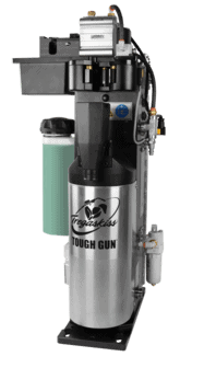
Finally, determine the best location for the nozzle cleaning station or reamer. This peripheral cleans the nozzle of spatter during routine pauses in welding. It helps extend consumable life and reduces downtime for changeover.
The reamer needs to be close enough for the robotic welding gun to engage fully for the ream cycle. If you’re operating two robots close together, you can program them both to use the same reamer. Avoid mounting the reamer anywhere but a flat surface, since positioning it at an angle can cause anti-spatter to leak over equipment or fixtures.
Avoid interrupting the weld cycle by cleaning the nozzle during robot idle time. For example, consider cleaning the nozzles while parts are being transferred in and out of the fixture or while components are being loaded into a weld cell.
Small Moves, Big Impact
If you’re experiencing bottlenecks or missing productivity or quality goals, take a look at the welding cell layout. In a semiautomatic setup, never overlook welder comfort and safety. In a robot cell, moving power cables, power sources, wire feeders, or anything else can change how much that cell can produce over a shift.
The little things matter, and missing just one detail can snowball into bigger problems down the road. Small changes can make a big impact on the efficiency you can achieve.
Written by Justin Craft (justin.craft@bernardwelds.com), Field Technical Services Specialist, Tregaskiss and Bernard, Republished with permission from The Fabricator (August, 2023).
Proper Robotic Welding Gun Configuration

Proper Robotic Welding Gun Configuration
Estimated reading time: 6 minutes
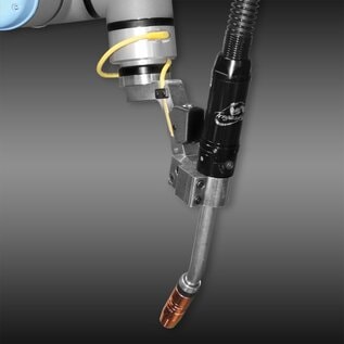
The welding gun is a vital piece of equipment in a robotic welding system, serving as the conduit for the welding wire, gas, and power. However, it can sometimes be an afterthought when companies implement an automated welding solution. Unfortunately, this oversight can lead to a host of problems, not to mention frustration. That is especially true for first-time users making the investment.

The wrong robotic welding gun can also cause issues for those more experienced with robotic systems. It’s not uncommon for companies to purchase the same gun for a new robot and tooling when, in fact, it may not be the best option.
Companies also need to determine their welding amperage and arc-on requirements for the application. This ensures that they purchase a robotic welding gun with the proper duty cycle — the amount of welding that can occur at a rated output over a period without causing damage to the gun.
Robotic welding guns are available in a variety of ratings, including air-cooled models that operate at 350 or 385 A at 100% duty cycle.
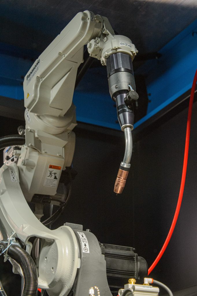
Today, most robotic welding systems are through-arm models in which the power cable runs through the casting of the robot arm. As a first step in configuring a robotic welding gun for these systems, it’s important to know the make and model of the robot, power source, and wire feeder. Each equipment manufacturer has a different interface that dictates how each piece of equipment connects with one another.
There are higher amperage water-cooled options, which are typically 400 A and above, available in the marketplace. Some of these may be rated at 100% duty cycle, while others are rated at 60%. Don’t be fooled by high amperage unless it’s at 100% duty cycle.
Hybrid options are available for companies that want the simpler construction of an air-cooled robotic welding gun with the added cooling capacity of a water-cooled one. These guns have external water lines that circulate water around the nozzle to keep the front-end consumables cooler.
For a robotic welding gun to access the weld joints, it’s critical that the work envelope is adequate. Companies need to consider not just the size of the gun but also the space that is available when the tooling, fixtures, and parts are all in place. Joint design and weld sequencing also factor into the equation. It’s important that there is room and time for the welding gun to weld the joints in a sequence that keeps heat to a minimum. Companies should avoid heat soaking the parts, so they don’t become distorted.
A robot integrator can conduct a 3D simulation using models provided by the robotic welding gun manufacturer through computer-aided design (CAD) to make sure the gun and neck have the proper access and reach within the given space. The CAD model can also show whether the selected gun has the correct tool center point (TCP) and can extend to the nozzle cleaning station for reaming or to a service window for consumable changeover. A service window supports safety in the operation by eliminating the need for an employee to physically enter the cell.
Configuring the Gun
Some robotic welding gun manufacturers offer online configurators that allow companies to customize the equipment for their exact application. These configurators guide the user through a step-by-step process, providing options to choose from for each component. With or without this tool, companies need to consider what their needs are based on their upfront assessment.
Gun mount: There are two mounting options for a robotic welding gun to protect it in the event of a collision — a solid arm mount and a clutch. If the robot or end user’s safety procedure requires external collision detection, a clutch can be added to the system. This component functions both mechanically and electrically by recognizing a collision and sending a message to the robot controller to stop the system. If procedures allow for reliance on only the robot’s collision detection, then a solid mount will suffice.
Neck: The neck length and angle must provide the approach angle to weld parts properly and to allow for smooth wire feeding. Standard neck angles are 22, 45, and 180 deg. Through-arm robots generally use a 45-deg neck; however, that should be verified with the CAD model/simulation before implementing. Companies will also need to take into consideration the welding wire they are using. For example, aluminum wire requires a straighter neck to feed through properly since it is so soft.
Welding cable: For through-arm robots, the make and model dictate the cable length. For conventional robots (where the cable assembly runs outside the robot arm), the gun cable length also depends on the robot make and model along with the location of the feeder. It may be remotely mounted or mounted on the robot itself. There is more flexibility with cable length for these robots, but it’s important not to use too long of a cable since this can lead to wire-feeding issues. Conversely, a cable that is too short can stretch and break down quickly.
Welding consumables: When choosing contact tips for the robotic welding gun, look at the welding process. Pulsed gas metal arc welding (GMAW-P), for example, is quite hard on contact tips due to its high-frequency waveforms. This process requires a harder tip or a contact tip specifically designed for pulsed welding.
The chosen nozzle needs to allow proper access to the weld joint. A tapered nozzle works well when using smaller-diameter wire and contact tips. Higher-premium consumables are a good choice since these last longer and reduce downtime and labor for changeover.
Welding supervisors and operators should schedule time to perform preventive maintenance, such as checking connections and visually inspecting consumables for spatter, during routine pauses in welding.
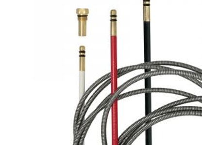
Liners are another factor to consider, and the welding wire being used affects the choice. Flux- and metal-cored wires tend to be stiffer and harder to feed than solid wires. They require an extra-heavy-duty liner to support the wire and gain smooth feedability as it moves toward the contact tip. A D-wound galvanized wire works well. Companies can also use this liner for solid wire with good success.
Maintaining Efficiency
Companies invest in robotic welding systems to increase quality, productivity, and cost savings through a fast, repeatable process. To gain those benefits, every part of the system needs to be functioning optimally. Ensuring that the robotic welding gun has been configured properly before implementing the system can prevent downtime and extra expenses.
This article was written by Ryan Lizotte (project manager, Tregaskiss, Windsor, Ontario, Canada) for the American Welding Society.
At a Glance: Cobots and the BA1 Cobot MIG Gun
At a Glance: Cobots and the BA1 Cobot MIG Gun
Estimated reading time: 4 minutes
Companies today continue to face a shortage of qualified welders, but the demand for product has stayed the same — or in many cases, increased. Turning to new solutions to keep up with production can help keep the welding operation running smoothly and quickly.

For many companies producing a high mix and low volume of parts, investing in a cobot can be a smart business decision. A cobot, or collaborative robot, relies on interaction from a welding operator but provides faster speeds than semi-automatic welding. Cobot welding is also a less expensive alternative to robotic welding and takes up less space.
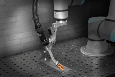
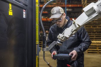
To operate the cobot, the welding operator uses a tablet to program the desired weld and moves the cobot welding gun to the beginning of the joint. While the cobot is welding, the welding operator can work on other activities, helping companies make the most of the available labor.
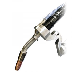
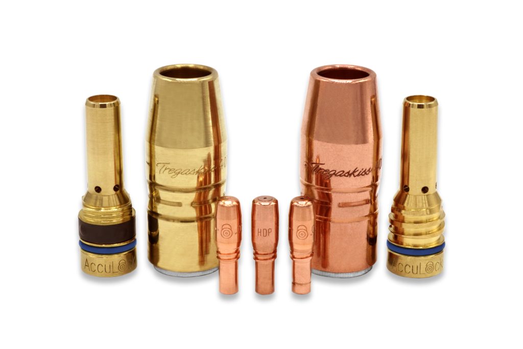
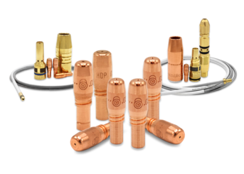
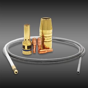
Tregaskiss BA1 cobot air-cooled MIG gun
Tregaskiss designed its BA1 cobot welding gun to help companies gain the most from their cobot. It provides several key benefits.
Durability
The BA1 gun is designed and engineered with the same trusted and robust components as other Tregaskiss guns and is proven to last in high-volume welding operations.
Productivity
Combined with AccuLock™ R consumables, the BA1 welding gun can help ensure greater productivity. The contact tips last longer so there is less downtime for changeover. When routine changeover is necessary, it can be done quickly and easily so the cobot and welding operator spend more time producing parts.
Reliability
The BA1 cobot MIG gun has metal-to-metal keyed connections to hold it in place in the mounting arm. These also keep the aluminum-armored neck firmly connected to the gun, so users can depend on the gun to perform consistently.
Simplicity
The gun is easy to maintain when needed — necks can be changed with one tool by loosening a small number of fasteners. Operators can also easily install QUICK LOAD® liners from the front of the gun. For operations that have semi-automatic welding, companies can streamline inventory by using the same AccuLock contact tip on their MIG guns.
Compatibility
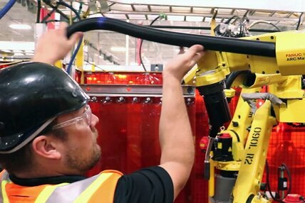
The BA1 cobot gun is compatible with cobots from FANUC®, Yaskawa® Motoman® and Universal Robots (UR) and most welding power sources. Power pin options are available for machines from Miller®, Lincoln®, Fronius®, Tweco®, Panasonic® and more.
Tregaskiss offers customizable options according to style and neck, consumables, cable length, wire size and power pin through the online configurator.
Cobot welding best practices
Along with having a reliable cobot MIG gun, there are some best practices to consider for cobot welding.
- Provide welding operators with proper training. Programming is relatively easy using a simple tablet interface, and training can be done quickly. In many cases, welding operators are able to share their knowledge with other employees to expedite training.
- Follow safety precautions and use proper Personal Protective Equipment (PPE). Read and follow the cobot and cobot gun owner’s manuals. The cell where the cobot is located should be surrounded by welding curtains to protect the operator and others from arc flash.
- Tooling, fixtures and other equipment added to the robotic cell after delivery may change the type and number of hazards present in and around the cobot system. Conduct a safety review and perform another risk assessment after the installation of any additional equipment to the robotic cell.
- Understand the rating of the gun and make sure that it is appropriate for the application and prevent overheating. The BA1 cobot gun offers 385 amps at 100% duty cycle with mixed gases.
- Be sure the robot and gun can move freely and that the power cable doesn’t interfere. Operators should also stand clear of the moving cobot.
- Understand the tool center point (TCP) and how far the cobot and cobot gun can reach to ensure quality.
As with any welding application, contact a trusted cobot welding gun or cobot manufacturer with questions or reach out to a local welding distributor.
Is a Water-Cooled Robotic Welding Gun Necessary?
Is a Water-Cooled Robotic Welding Gun Necessary?
Robotic welding operations can be tough on equipment. The heat from the welding arc, along with reflective heat from the base material and resistive heat from the electrical components, can wear on consumables and the robotic welding gun. In some cases, implementing a water-cooled robotic MIG gun is the answer, but many times an air-cooled model can handle the job.
Water-cooled robotic welding guns are designed to handle high amperage applications, typically above 400 welding amps at 100% duty cycle. They are used for longer welds and multiple passes on thicker material with larger welding wire diameter (above 0.052 inch), such as those found in heavy equipment manufacturing.
That said, water-cooled guns are more expensive upfront compared to their air-cooled counterparts and require the additional expense of a water cooler. These guns operate by circulating a coolant from the water cooler through hoses in the power cable to the gun and neck, then returning the coolant to the cooler to release the absorbed heat. Due to the complexity of this design, there are more potential failure modes, so maintenance and repairs cost more over the life of the gun. Given the current shortage of skilled labor, it can be difficult to find welding operators who can take on these tasks. That can lead to downtime and lost productivity.
For these reasons, companies need to ask: Is a water-cooled welding gun necessary? Often, companies may be using this type of gun because it’s what’s always been on the plant floor, or they think they need the extra protection from the heat of the application. They may even be trying to protect the consumables from overheating. That doesn’t mean that a water-cooled welding gun is the best option.
When air-cooled makes more sense
Air-cooled robotic welding guns use the ambient air, shielding gas and arc-off time to dissipate heat. Their design is simple and easy to maintain since they have fewer parts than water-cooled models. A lower upfront cost and less expense to care for the guns make them an appealing alternative to a water-cooled gun. And, in several instances, these guns are a better option for a welding operation.
Duty cycle factors into using an air-cooled robotic welding gun. Duty cycle refers to the number of minutes a welding gun can operate at full capacity in a 10-minute period without overheating. If the gun can operate the full 10 minutes, then it offers 100% duty cycle. However, many applications do not require 100% duty cycle and therefore wouldn’t benefit from a water-cooled gun that offers that capacity. In this case, it is possible to use a 350-amp air-cooled gun and run it at a lower duty cycle: for example, 50%. An air-cooled robotic MIG gun will heat up and plateau at a certain temperature. The operator overseeing the application will need to be cognizant of the duty cycle and welding duration and adjust the application accordingly.
In applications with shorter weld requirements, it’s also possible to configure a robotic welding cell to use air-cooled robotic welding guns. On a robotic line, there are often multiple robots welding at the same time. If one robot only welds for one minute and a second robot welds for two minutes, then the air-cooled gun on the first robot has time to cool down as it waits for the other robot to finish its weld. In essence, the robotic welding gun on the first robot would be working at 50% duty cycle as compared to the second robot.
For companies using a water-cooled robotic MIG gun to keep consumables from overheating, a simple change of consumable type combined with an air-cooled gun is a better, and less costly, option. Consider changing from a copper contact tip to a chrome zirconium, since it can withstand heat better. Also, high-performance consumables like AccuLock™ HDP contact tips can significantly extend tip life, even in hard pulsed robotic welding applications. They can last six to 10 times longer than copper and chrome zirconium tips. While these contact tips have a higher upfront cost, the lower expense of an air-cooled robotic welding gun means the reduction in downtime and higher productivity saves money in the long term.
Simplifying the robotic welding operation
The goal of investing in robotic welding is to increase productivity, improve quality and reduce costs. Using an air-cooled robotic welding gun, when possible, can help companies gain these benefits. The lower upfront cost and total cost of ownership of this equipment means a better bottom line.
From Consumables to Communication: Reducing Human Error in Welding
From Consumables to Communication: Reducing Human Error in Welding
Estimated reading time: 4 minutes
Human error can take its toll on welding operations, leading to downtime and lost productivity, poor quality and increased costs. It can result from a variety of factors. An operator may know how to manage a process, but periodically misses a step or forgets to complete a task. Or an operator may believe he is conducting a task in the correct manner, but it is wrong.
To reduce problems, it’s important to provide proper training to semi-automatic and robotic welding operators. This includes not only training on the welding process, but also on how to spot errors when they occur.
Companies may want to rely on principles of poka-yoke to help. These principles could be applied in several ways in a welding operation.
- Elimination: Remove or change parts of the welding process that cause problems
- Prevention: Investing in equipment or processes that prevent errors
- Replacement: Substitute consumables with ones that are more consistent
- Facilitation: Streamline operations to reduce the risk of a welding operator causing an error
- Detection: Identify errors early and correct them before they lead to costly rework
- Mitigation: Find ways to reduce the impact of errors on the welding operation
With these high-level, error-proofing ideas in mind, it’s possible to put them into action in several specific ways.
Color-coded parts
Investing in welding consumables with color-coded parts can help eliminate confusion during installation. AccuLock™ S liners and power pin caps are color coded to make it easy to identify which power pin cap is compatible with which liner. For example, power pin caps with red washers are compatible with liners that have red shrink tube and so on.
Welding procedures
Implementing a welding procedure specification (WPS), and training operators to follow it, can help ensure consistent, high-quality welds. A WPS outlines details on the welding process and parameters, weld pass sequences, filler metal type and size, and more.
Error-proof consumables design
For operations with a mix of welding arcs or for all automated welding operations, AccuLock R consumables are designed to prevent errors associated with cross threading during installation. They feature a long contact tip tail that aligns in the diffuser prior to the thread engaging. This allows operators to install the tip easily and accurately. The AccuLock S welding gun liner also offers error-proof liner trimming with no measuring required for semi-automatic welding operations.
Long-lasting consumables
Consumables that last longer require less changeover, which means less interaction by the welding operator in the welding cell and less potential for errors. AccuLock contact tips offer a longer lifespan, particularly the AccuLock HDP tips. These last up to ten times longer than standard contact tips and are designed for use in pulsed MIG welding applications, where waveforms tend to be harsher on tips.
Inventory reduction
Taking steps to simplify inventory by having a lower variety of consumables can help prevent errors during changeover. The AccuLock S and AccuLock R consumable systems share a common contact tip, so the tip can be used in Bernard semi-automatic MIG guns and Tregaskiss robotic and fixed automatic guns.
Communication and reporting
Keeping open lines of communication among welding operators and with management is an important way to minimize and rectify errors. Knowing what is expected in the welding process is a good start, as is reporting errors when they occur so that they can be fixed and don’t lead to further complications.
Preventing errors in a welding operation requires attention to detail, a commitment to making improvements, and collaboration among welding operators and management. Everyone needs to take a vested interest in the process, knowing that it will help improve quality and productivity — and ultimately make everyone’s job easier.
Choosing Between Fixed Automatic, Cobot and Robotic Welding
Choosing Between Fixed Automatic, Cobot and Robotic Welding
Estimated reading time: 5 minutes

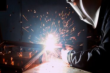
No doubt manual, or semi-automatic, welding has its place across the industries — general fabrication and manufacturing, shipbuilding and more — and it will continue to be an important process for many applications. There are times, however, when companies need to turn to welding automation to augment or replace portions of their operations. Some may benefit from fixed welding automation, while other operations lend themselves to either cobot welding or automated (robotic) welding.
At a high level, companies tend to move to one of these types of welding processes for similar reasons: to improve quality, increase welding productivity and/or lower costs. Some companies may be responding to an increase in demand from customers or want to gain a competitive edge by supplementing their operations with automation. In certain cases, companies may replace some semi-automatic welding cells, shifting welding operators to oversee the automated operation. These systems always require interaction with an operator for loading and unloading parts, programming and troubleshooting when necessary.
To implement the right solution and successfully operate it requires careful planning. A robotic integrator or equipment manufacturer can help, and they can also provide a thorough calculation to help determine the expected return on investment (ROI).
So, when is it time to add an automated welding solution? And which one is the best for a given application?
Fixed automation
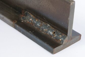
Companies that find themselves with very large parts that are difficult to weld in a timely or repeatable manner with a semi-automatic process may want to consider fixed welding automation. This process is well suited to high-volume operations with a low variety of parts, such as structural beams or railcars requiring long, continuous welds or pipe that requires circular welds. The investment in fixed welding automation equipment is relatively low, but it can provide a reliable payback by increasing productivity.
Companies can choose from two options:
- Tooling that holds the part in place combined with a fixed automatic welding gun that moves the length of the weld joint on a track. This is a good option for long, linear welds.
- A fixed automatic welding gun held in place by tooling while the part moves. This setup works well for pipe, which can be rotated.
Because there isn’t a lot of flexibility with tooling, companies investing in fixed welding automation need to consider their long-term plans and the parts they will produce.
Cobot welding
Companies seeking greater versatility in their high-mix, low-volume operations or those needing to produce longer welds than possible with a semi-automatic process could benefit from cobot welding. Those who are interested in the faster speeds associated with welding automation but have limited space or capital to invest may also want to consider the switch. Cobot welding systems are less expensive than robotic welding systems, have a smaller footprint and don’t require the guarding that a robot would.
Since a welding operator works side by side with the cobot, he or she can be in the cell with the equipment with a relatively low safety risk. Cobots are also portable, allowing companies to address multiple applications in the facility without the need to invest in additional equipment.
Training requirements are minimal compared to robotic welding, with straightforward programming on a tablet, and setup is relatively quick. These factors are important for companies struggling to find and retain skilled labor and those seeking productivity increases.
During operation, the operator sets the cobot welding gun at the starting point to put the welding in motion. The cobot is designed to complement the work that the welding operators are doing and allows them to attend to other tasks like grinding while the cobot is welding.
Robotic welding
When a company is falling short of its production goals, experiencing weld quality issues or facing increased customer demands, it may be time to invest in a robotic welding system. While smaller operations can benefit from this process, robotic welding systems especially excel at high-volume, low-variety applications. The facility must have the appropriate space available; robotic welding cells typically take up more room than a cobot or a semi-automatic welding cell.
An advantage of robotic welding, in addition to speed and repeatability, is the relatively quick ROI. To gain that, however, it’s important that the parts coming from upstream are consistent — gaps or poor fit-up can hinder the operation — and that there are no bottlenecks that would make the robot stay idle. An electronic CAD model of the part can help determine if a part lends itself to repeatability.
As with fixed welding automation and cobot welding, it’s imperative to have a welding operator involved with a robotic welding system. Parts need to be loaded and unloaded, and the robot requires programming. Robot integrators and manufacturers typically offer training to help ensure success.
Making the switch
Whether a company is a candidate for fixed welding automation, cobot welding or robotic welding, taking the time to carefully plan for the investment is important. Look to a trusted welding distributor, robot integrator or equipment provider for assistance and for help determining the expected payback.
Solving Common Causes of Welding Porosity
Solving Common Causes of Welding Porosity
Estimated reading time: 7 minutes
Porosity, cavity-type discontinuities formed by gas entrapment during solidification, is a common but cumbersome defect in MIG welding and one with several causes. It can appear in semi-automatic or robotic applications and requires removal and rework in both cases — leading to downtime and increased costs.
The major cause of porosity in steel welding is nitrogen (N2), which gets involved in the welding pool. When the liquid pool cools down, the solubility of N2 is significantly reduced and N2 comes out of the molten steel, forming bubbles (pores). In galvanized/galvanneal welding, evaporated zinc can be stirred into the welding pool, and if there is not enough time to escape before the pool solidifies, it forms porosity. For aluminum welding, all porosity is caused by hydrogen (H2), by the same way as N2 works in steel.
Welding porosity can appear externally or internally (often called sub-surface porosity). It can also develop at a single point on the weld or along the entire length, resulting in weak welds.
Knowing how to identify some key causes of porosity and how to quickly solve them can help improve quality, productivity and the bottom line.
Poor Shielding Gas Coverage
Poor shielding gas coverage is the most common cause of welding porosity, as it allows atmospheric gases (N2 and H2) to contaminate the weld pool. Lack of proper coverage can occur for several reasons, including but not limited to poor shielding gas flow rate, leaks in the gas channel, or too much air flow in the weld cell. Travel speeds that are too fast can also be a culprit.
If an operator suspects poor flow is causing the problem, try adjusting the gas flow meter to ensure the rate is adequate. When using a spray transfer mode, for example, a 35 to 50 cubic feet per hour (cfh) flow should suffice. Welding at higher amperages requires an increase in flow rate, but it’s important not to set the rate too high. This can result in turbulence in some gun designs that disrupts shielding gas coverage.
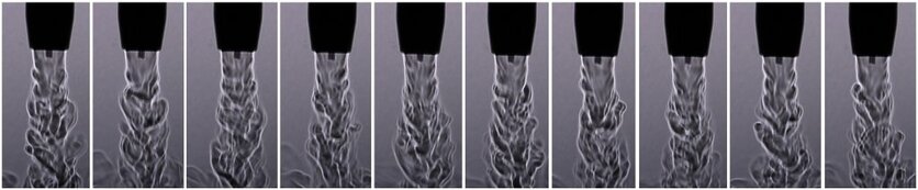
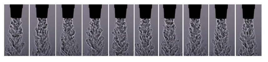
It’s important to note that differently designed guns have different gas flow characteristics (see two examples below). The “sweet spot” of the gas flow rate for the top design is a lot larger than that of the bottom design. This is something a welding engineer needs to consider when setting up the weld cell.
Also check for damage to the gas hose, fittings and connectors, as well as O-rings on the power pin of the MIG welding gun. Replace as necessary.
When using fans to cool operators or parts in a weld cell, take care that they are not pointed directly at the welding area where they could disrupt gas coverage. Place a screen in the weld cell to protect from external air flow.
Re-touch the program in robotic applications to make sure there is a proper tip-to-work distance, which is typically ½ to 3/4 inch, depending on the desired length of the arc.
Lastly, slow travel speeds if the porosity persists or consult a MIG gun supplier for different front-end components with better gas coverag
Base Metal Contamination
Base metal contamination is another reason porosity occurs — from oil and grease to mill scale and rust. Moisture can also encourage this discontinuity, especially in aluminum welding. These types of contaminants typically lead to external porosity that is visible to the operator. Galvanized steel is more prone to subsurface porosity.
To combat external porosity, be certain to thoroughly clean the base material prior to welding and consider using a metal-cored welding wire. This type of wire has higher levels of deoxidizers than solid wire, so it is more tolerant of any remaining contaminants on the base material. Always store these and any other wires in a dry, clean area of similar or slightly higher temperature than the plant. Doing this will help minimize condensation that could introduce moisture into the weld pool and cause porosity. Do not store wires in a cold warehouse or outdoors.
When welding galvanized steel, the zinc vaporizes at a lower temperature than the steel melts, and fast travel speeds tend to make the weld pool freeze quickly. This can trap zinc vapor in the steel, resulting in porosity. Combat this situation by monitoring travel speeds. Again, consider specially designed (flux formula) metal-cored wire that promotes zinc vapor escape from the welding pool.
Clogged and/or Undersized Nozzles
Clogged and/or undersized nozzles can also cause porosity. Welding spatter can build up in the nozzle and on the surface of the contact tip and diffuser leading to restricted shielding gas flow or causing it to become turbulent. Both situations leave the weld pool with inadequate protection.
Compounding this situation is a nozzle that is too small for the application and more prone to greater and faster spatter buildup. Smaller nozzles can provide better joint access, but also obstruct gas flow due to the smaller cross-sectional area allowed for gas flow. Always keep in mind the variable of the contact tip to nozzle stickout (or recess), as this can be another factor that affects shielding gas flow and porosity with your nozzle selection.
With that in mind, make sure the nozzle is large enough for the application. Typically, applications with high welding current using larger wire sizes require a nozzle with larger bore sizes.
In semi-automatic welding applications, periodically check for welding spatter in the nozzle and remove using welder’s pliers (welpers) or replace the nozzle if necessary. During this inspection, confirm that the contact tip is in good shape and that the gas diffuser has clear gas ports. Operators can also use anti-spatter compound, but they must take care not to dip the nozzle into the compound too far or for too long, since excessive amounts of the compound can contaminate the shielding gas and damage the nozzle insulation.
In a robotic welding operation, invest in a nozzle cleaning station or reamer to combat spatter buildup. This peripheral cleans the nozzle and diffuser during routine pauses in production so that it does not affect cycle time. Nozzle cleaning stations are intended to work in conjunction with an anti-spatter sprayer, which applies a thin coat of the compound to the front components. Too much or too little anti-spatter fluid can result in additional porosity. Adding in air blast to a nozzle cleaning process can also aid in clearing loose spatter from the consumables.
Maintaining quality and productivity
By taking care to monitor the welding process and knowing the causes of porosity, it’s relatively simple to implement solutions. Doing so can help ensure greater arc-on time, quality results and more good parts moving through production.
Pulsed Welding and Through-Arm Robots: What to Know

Pulsed Welding and Through-Arm Robots: What to Know
Estimated reading time: 6 minutes
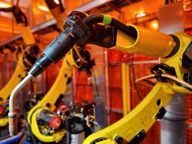
After early adoption by the automotive industry, the combination of pulsed gas metal arc welding (GMAW) and through-arm robots has become a more common part of automated welding operations in general manufacturing and fabrication. In fact, through-arm robots have largely replaced conventional ones in the last decade as more robot OEMs lean toward that design.
Pairing this type of robot with pulsed MIG welding can help companies improve productivity and quality. Through-arm robots, as their name implies, feature a hollow upper-arm casting that allows the welding power cable to run through the center. This design eliminates the need for the cumbersome cable management usually associated with conventional robots. Routing the cables through the arm also prevents them from getting caught on tooling or parts. The design improves joint access by reducing the overall size and shape of the robotic welding gun (i.e., end-of-arm tooling). Pulsed welding enhances the benefits of this combination by helping lessen part distortion, minimizing burn-through — especially in instances when the robot’s tool center point (TCP) is off — and reducing spatter.
The pulsed welding waveforms, however, can create wear on the through-arm robot’s welding gun components, such as welding consumables and welding power cables. Companies need to consider several factors during their selection and operation to gain consistent results and help these components last.
Understanding the impact of pulsed waveforms
Pulsed welding works well for lap joints on thinner materials, which is why it is prevalent in the automotive industry. Galvanized steel used for vehicle body skins, for example, may be as thin as 0.7 millimeters. Pulsed welding can also be used for thicker materials, up to and beyond 1/4 inch, with good results.
This welding transfer mode operates as a modified spray transfer process and requires a power source with specific pulsing capabilities. During operation, the welding output switches rapidly between high peak and low background currents. The peak current is responsible for pinching off the molten droplet from the filler metal and easing it toward the weld joint. While this is happening, the background current keeps the arc on and stable but is too low to transfer any filler metal. The weld pool cools slightly while the low background cycle occurs.
While pulsed welding offers benefits that support quality, the waveforms also cause a higher level of electrical and thermal stress on the through-arm robot’s welding power cable, since it is confined within the arm of the robot as opposed to being externally routed over the arm. The waveforms can also be harsh on welding consumables — particularly contact tips.
Impact on Contact Tips
The peak amperage values in a pulse waveform can cause micro-arcing inside the contact tip, which leads to higher resistance and ultimately burnback or the fusing of wire inside the bore of the contact tip. Chrome zirconium contact tips are slightly harder than copper tips and resist mechanical wear better in CV applications. However, a pulsed-welding-specific contact tip is needed to combat the electrical wear and micro-arcing and extend tip life in pulsed welding applications.
Impact on Welding Power Cables
Pulsed waveforms can be similarly hard on the welding power cable in a through-arm robot. Variations in welding joint access can put stress on the cable as the robot arm articulates, which can affect the current path. Again, the amperage peaks associated with pulsed waveforms can transfer across any open connections. If electrical resistance is high, the current will travel toward an easier path, leading to damage to the copper within the cable and burnt or shorter liners.
Unfortunately, it is difficult to predict cable failure in a pulsed welding application since there are few indicators. Periodically, the liner may become fused within the welding power cable or become discolored due to the current taking the liner as the path of least resistance as the power cable fails. If any cracks in the power cable jacket or exposed copper appear, it is time to replace the cable.
Ways to combat wear
There are steps companies can take to help minimize wear caused by pulsed waveforms to make through-arm robot components last longer.
1. Use Contact Tips for Pulsed Welding
As mentioned previously, companies can look for contact tips designed specifically for pulsed welding. These are made from materials that better resist electrical stress and also tend to have a tighter inside diameter (ID) in the bore to reduce the opportunity for the welding wire to float. This helps the contact tip conduct electricity much more efficiently and for longer while maintaining a tighter TCP. These contact tips can also help minimize burnback.
2. Check Contact Tip to Work Distance
Paying attention to contact-tip-to-work distance (CTWD) is also important. It needs to be consistent along the entire length of the weld joint. This supports correct parameters in the pulsed welding process and reduces spatter that could shorten the life of the contact tip.
3. Select the Best Welding Power Cable
Welding power cables with a dynamic or sliding electrical connection help ensure electricity can pass through uninhibited even when the cable experiences mechanical stress from the robot’s movements. This improves the ability of the pulsed waveform to transfer current more efficiently. Companies should also select a power cable with reliable, consistent electrical connections and consider replacing the cable annually in high-production environments.
4. Improve the Robot Arm Path
Improving the path of the robot arm, to ease extreme bending and twisting at joints five and six (J5/J6), is another way to minimize power cable wear. There are means to program the through-arm robot so that it can reach the weld joints efficiently without impacting cycle time. Often the movements that companies need to change the most are air moves and wait or clear positions. The key is to use the robot arm in the most neutral position to reduce stress on the welding power cable, which can be done by minimizing the articulation of J5/J6 during welding and/or air movements.
Gaining the best results
In the right application, pulsed welding with a through-arm robot can help companies improve weld quality and productivity. Working with a trusted robot integrator, distributor and/or welding gun manufacturer can help ensure that the proper consumables and welding power cables are in place, as well as assist in programming the robot to provide the most efficient movements.
Republished Welding Journal (August 2022) with permission from the American Welding Society (AWS). Click here to view the original article.
The Value of Welding Consumables Trials
The Value of Welding Consumables Trials
In both semi-automatic and automated welding cells, the upfront cost of welding consumables is low compared to the overall expense for equipment, materials and labor. Yet when companies accrue downtime for excessive welding contact tip changeover or troubleshooting poor wire feeding associated with liner issues, costs can quickly compound.
At times, companies may try to mitigate consumable problems without a true sense of the root cause, implementing a solution without data to back up the decision. However, conducting a welding consumables trial can provide insight into whether an operation is using the best consumables for the application.
Welding contact tips are the baseline for these trials since they are the most frequently changed consumable. Nozzles and diffusers that are compatible with the contact tip are included in a trial but not monitored in the same way since they last much longer.
This article has been published as an exclusive with The Fabricator. To read the entire article, please click here.
Understanding the Impact of Time Sinks in Robotic Welding
Understanding the Impact of Time Sinks in Robotic Welding
Estimated reading time: 7 minutes
No robotic welding cell operates at 100% capacity. Parts handling, fixturing, periodic rework and even employee breaks all affect a robot’s ability to be completely efficient. However, there are common time sinks that can further hinder productivity — and they can easily lead to increased costs and lower quality.
Time sinks are activities that consume a lot of time for little benefit. So why do these happen? It could be a lack of training or lack of skilled labor. Or it could be simply out of habit; some activities may fall into the “we’ve always done it this way” category.

The key is to take steps to rectify these issues quickly, as they can easily escalate. That is especially true on large production lines. If one robot has an issue, it may result in having to stop an entire line of robots to solve the problem, compounding downtime.
Streamlining the process
Downtime for certain activities in a robotic weld cell is unavoidable, but they become time sinks when they aren’t streamlined. Welding contact tip changeover is a prime example.
While regular changeover is imperative to producing quality parts, it is not uncommon for operators to replace a contact tip before it is necessary. It can become a habit to change the tip every few hours, during breaks and before and after shifts without truly knowing whether there is still life left in the consumable. This frequency interrupts production, resulting in fewer parts being made and increased costs for the tip itself.
Conducting a time study to determine the true life of a contact tip — from installation to the point of failure — can help companies avoid excessive changeover and costs. The study may be time-consuming initially, but it can be conducted in one robotic welding cell to establish a baseline and then applied to similar cells.

It’s also recommended to try different types of contact tips to ensure that the best option is in place. For example, pulsed MIG welding applications are especially harsh on tips, so it’s essential to have an option for that waveform, like the AccuLock™ HDP contact tips, to extend product life. There is a higher upfront cost for these tips, but also a significant increase in productivity and throughput due to significantly less-frequent changeover.
Reaming too often can also become a time sink in a robotic welding cell. A nozzle cleaning station (or welding reamer) is necessary to clear spatter from the front-end welding consumables and ensure smooth gas flow, but it’s important to determine the optimal frequency for the application. For example, if a robot completes a 2-inch weld and then spends 10 seconds to ream, spray anti-spatter, nozzle-check and wire-cut, that is likely too often. Instead, it may be possible to weld 10 to 20 parts between reaming cycles. Again, a time study can help determine the appropriate frequency.
Common time sinks and tips for avoiding them
True time sinks may not be immediately obvious and the activities themselves may appear benign, but they can have consequences that result in extra time, labor and costs for welding troubleshooting. Fortunately, there are options to rectify these issues.

1. Poor wire conduit management
Due to the high volume of parts that pass through a robotic welding cell, most companies employ large welding wire drums to minimize changeover of these packages. Poor management of the conduit leading from the drum to the robot can lead to time sinks. If this conduit is too long, has been placed around the corner or snakes and bends along the floor, the wire won’t feed properly. Poor wire feeding can lead to burnbacks that require downtime for welding contact tip changeover. It can also cause the arc to become erratic, which causes quality issues and potential rework. The best way to resolve this issue is to keep the conduit as straight as possible and use the shortest run feasible.
2. Incorrect robot positioning and neck selection
Many large companies, such as tier-one automotive suppliers, measure their efficiency based on available square footage, so placing many robots in an area is common. This helps meet high production goals. However, if a company positions the robot incorrectly in relation to the tooling, it can increase robot articulation and lead to premature cable failure. The same holds true when using the wrong robotic MIG gun neck. While companies often like to standardize on one neck angle throughout the operation, it may not allow the robot to articulate properly to reach the weld joint.
As a best practice, the robot riser should be sized to minimize the amount of joint articulation when accessing the tooling. This reduces stress on the robotic MIG gun and the power cable. Select the appropriate neck angle to achieve the best joint access.
3. Troubleshooting on the line
When something goes wrong in a robotic welding operation, often the first instinct is to try to troubleshoot the issue on the spot. Doing so yields little benefit since it stops production: not just because the robot isn’t working, but also because multiple personnel may be stepping away from their jobs to address the problem. That adds up to unnecessary time and money spent.
A better option is to remove and replace the component causing the trouble, whether it be the robotic MIG gun or a welding reamer. That allows the robot to go back to work producing parts, while maintenance troubleshoots and repairs the equipment issue offline.
4. Overlooking preventive maintenance (PM)
Like troubleshooting on the line, reactive maintenance can be a significant time sink. Addressing unexpected problems keeps the robot from its job of producing parts. Also if something goes wrong within the weld cell because PM wasn’t performed, it can lead to poor quality parts, rework or costly repairs.
Instead, welding supervisors and operators should schedule time to perform preventive maintenance, such as checking connections and visually inspecting consumables for spatter during routine pauses in welding. More time-consuming PM activities, like replacing a gun liner, a robotic MIG gun or cable, or cleaning the robot, can happen between shifts or during other planned downtime.
Making a difference
When there are jobs to be done, it’s easy for companies to focus on moving production along and sending parts out the door. In the process, time sinks can occur that may be overlooked for long periods of time, compounding their severity.
However, pausing to look at the robotic welding operation and setting plans in place can help create efficiencies in the long run. In addition to time studies, conducting a process failure mode analysis (PFMA) can help by considering anything that could go wrong in the robotic welding cell. These situations are then ranked by potential frequency and severity and a plan put in place for addressing them.
It’s also important to remember that changes and improvements aren’t one-time occurrences. They must be monitored regularly and adjusted as needed. Coordinating a continuous improvement team to spearhead the process can help, as can working with a trusted welding equipment or robot manufacturer.
8 Manufacturing Cost-Reduction Strategies for Welding Operations
8 Manufacturing Cost Reduction Strategies for Welding Operations
Cost overruns in a manufacturing welding operation can come from many places. Whether it’s a semi-automatic or robotic weld cell, some common culprits of unnecessary costs are unplanned downtime and lost labor, consumable waste, repairs and rework, and lack of operator training.
Many of these factors are tied together and influence each other. A lack of operator training, for example, can result in more weld defects that require rework and repair. Not only do repairs cost money in additional materials and consumables used, but they also require more labor to do the work and any additional weld testing.
Repairs can be especially costly in an automated welding environment, where constant progression of the part is crucial to overall throughput. If a part isn’t welded correctly, it may still continue through all steps of the process. If the defect isn’t caught until the end of the process, all the work must be redone.
Companies can use these eight tips to help optimize consumable, gun and equipment performance — and reduce costs in both semi-automatic and robotic welding operations.
This article was published as an exclusive on thefabricator.com. Read the full article here.
Cobots and Cobot MIG Guns: What To Know for Manufacturing Welding Operations
Cobots and Cobot MIG Guns: What To Know for Manufacturing Welding Operations
Traditional robotic welding systems can deliver many benefits, but they aren’t always the right solution for every manufacturer. In applications where implementing a robotic weld cell isn’t the answer, some companies are turning to collaborative robots, or cobots.
While not new to the industry, cobots are currently a fast-growing and still-developing technology. They can help operations save time, improve part quality and deliver consistency — all at a lower investment cost than a robotic welding system.
Knowing the basics goes beyond just the equipment itself. It’s also important to understand how cobot welding gun and consumables selection play key roles in optimizing this technology.
Why cobots?
Cobots are still industrial robots, but they are designed to operate safely alongside workers and enable human collaboration with the robot. As an example, a cobot may be welding a workpiece while the nearby operator inspects and cleans a weld that was just completed by the cobot — essentially turning one worker into two.
Manufacturers with high-mix, low-volume production (those that make smaller numbers of a wide variety of parts) are a good fit for cobots, making general manufacturing and job shops common adopters.

There are several benefits that can help operations save time and money while improving part quality. These include:
1) Lower total cost
Cobots are typically less expensive for operations to adopt compared to a fully automated welding cell. This includes the initial cost of the equipment and the training required to get operators up to speed for programming and using it. In addition, many companies that provide robot integration offer leasing options for cobots, making it easy for manufacturers to try out the solution before making a purchasing decision.
2) Ease of use and training
Cobots have intuitive touch-screen user interfaces and are significantly easier to use than traditional robotic welding cells. Operating a cobot requires some training, but little welding or programming experience is necessary to successfully operate it. Compare that to a traditional robotic welding cell, which typically requires more extensive welding or programming experience. The reduced level of training with cobots can be a plus for operations that struggle to find and retain skilled labor.
3) Reduced safety risks
Because cobots are designed to be operated with human interaction, they have many built-in safety measures. They are limited in how fast they can move, are very sensitive to collisions, and they do not have pinch points. They will stop movement in the event of a collision. And because of these design parameters, the cobots will not be moving very fast if they do collide with something. Cobots can be programmed to move faster when they are not working alongside a human.
4) Portability
Many cobots are portable — essentially a table with a robot on it. They can be moved elsewhere in the facility to be used where they are needed. This allows operations to easily change which production line is using it.
Implementing cobots
Cobots are designed to offer a low barrier to entry — with fast setup and high ease of use. The programming required and specifics of the user interface will vary based on the integrator, but often the cobot is controlled by a tablet or cell phone app — making training and programming very easy. Some cobots are assembled before they are shipped, so setup only takes 30 minutes to an hour.
Once set up, operators can move the cobot to exactly the spot they want to start the weld and push a button to save that point. Then they can move the cobot to the end point of the weld and save that point. This can be easily repeated for each weld.
Some cobots allow the addition of different features to the programming, such as seam welds or stitch welds.
Choosing a welding gun and consumables
While it’s easy for the selection of a welding gun and consumables to be an afterthought in the process, these play an important role in the performance and efficiency of any welding system, including a cobot.
Choose a high-quality gun and consumables to optimize results, provide longer product life and reduce the time and money spent on troubleshooting. Reducing consumable changeover and potential issues is especially important for companies with less-experienced operators.
MIG guns for cobots are tested and rated using the same standards applied to traditional MIG guns. Be aware of what the rating means when selecting a MIG gun for cobot welding, as it helps prevent overheating when guns are used as they are rated.
A gun like the Tregaskiss BA1 cobot MIG gun features metal-to-metal connections that hold it in place in the mounting arm and keep the aluminum-armored neck firmly connected in the gun body to ensure accurate, quality welds. It also has minimal fasteners and a precision-machined keyway mounting system, making installation of the gun and mounting arm quick, easy and accurate.
To simplify maintenance, consider a front-load liner, since these can reduce downtime for changeover. The liners are replaced from the front of the gun without disturbing the gun, wire or feeder connection. Liner issues and challenges with liner replacement are a common cause of troubleshooting with both cobot MIG guns and traditional robotic ones. Having an easier liner replacement process helps reduce or avoid problems.
Look for consumables, like AccuLock™ R contact tips, nozzles and gas diffusers, that are designed to maximize production uptime through long service life and quick replacement. Since contact tip cross-threading issues can be a source of downtime in welding operations — especially with less experienced welding operators — these consumables feature coarse tip threads that help to eliminate the problem. They also feature increased mass and are buried within the diffuser, away from the weld, to increase tip life.
Cobots in welding
In the right manufacturing operation, cobots can help improve productivity and efficiency and lessen the strain on operations having difficulty finding skilled welders.
However, users expect a quick-to-implement and easy-to-use solution that keeps their operations agile and profitable. Choosing durable, high-quality cobot MIG guns and consumables for a cobot system can keep operators focused on manufacturing quality parts instead of troubleshooting or maintenance. This helps operations achieve their productivity and quality goals — and get the results they want.
5 Tips for Robotic Welding Process and Project Planning
5 Tips for Robotic Welding Process and Project Planning
Robotic welding projects can arise in a number of ways — from a smaller shop expanding its capabilities to a large original equipment manufacturer (OEM) awarding new business or even a new company establishing itself within the competitive landscape.
Regardless of the circumstances, it’s critical to implement a well-thought-out and thoroughly researched plan to ensure a successful robotic welding operation. The plan should cover both the details related to the welding process and the specific project at hand. This helps companies meet quality and productivity goals while maintaining their cost margins and achieving profitability.
Being proactive is the key with planning. Doing so helps minimize the opportunity for unforeseen risks that could be detrimental to the welding operation. Some basic tips can help along the way.
Tip No. 1: Ask questions
To determine the desired outcome for a robotic welding operation, it’s important to define the welding process — in terms of how efficient and quick it needs to be — and to consider all details related to the project’s budget. Asking some fundamental questions can help stakeholders define the scope of the process they are using and the project they are undertaking.
- What efficiencies do we need from the welding process?
- How labor-intensive will the process be?
- Is there adequate staff for loading/unloading fixtures?
- What training will staff need to keep the robot welding effectively?
- How many robots do we need? And how hard or long do we want the robots to work?
- What should we consider about the weld cell ergonomics?
- How should the robots be configured?
- What capital is available and how fast do we want our return on investment (ROI) to be?
Answering these questions can help companies as they plan out their project and conduct cost analysis.
Tip No. 2: Set realistic goals
Along with asking questions to set the foundation for solid process and project planning, it’s also important to set realistic goals. These goals should relate to general processes in the robotic weld cell along with desired quality outcomes.
For example, when considering the capabilities of the welding process in a robotic cell, a 75% to 80% efficiency rate may be a realistic goal. No welding process is 100% efficient, so it’s important to account for equipment downtime (planned or unplanned), consumable changeover, welding wire drum changeover and more.
The same holds true for quality goals. Having 100% quality isn’t necessarily true to life since weld defects like porosity can occur, tool center point (TCP) can shift and stampings can become misaligned. Each of these instances is possible (and probable) in an everyday robotic welding operation.
Setting realistic goals allows time for unexpected occurrences once the robotic welding system is at work.
Tip No. 3: Look at the long term
While it may be tempting for companies to look for ways to reduce upfront costs during process and project planning, this doesn’t ensure that the long-term results are always positive. For example, neglecting to consider (and purchase) supplemental equipment, such as reamers (also called nozzle cleaning stations), can lead to greater expenses over the lifetime of a project.
Reamers clean spatter from the welding gun nozzle and gas diffuser to ensure smooth shielding gas flow that in turn supports good weld quality. Reamers are available in analog or ethernet models.
It’s important to consider reamer quality, especially for heavy-duty, higher-volume applications. While reamers with heavy-duty construction generally cost more, they also last much longer than light-duty models. Be sure to size the reamer appropriately for the project because reamers vary in the amount of torque they provide when removing spatter. Heavy-duty reamers provide more torque and have cutter blades that can reach deeper into the nozzle for a more thorough spatter cleaning.
Companies should also determine how much human interaction with the reamer is necessary to keep the welding process at target efficiency levels. For example, implementing a multi-feed anti-spatter sprayer system reduces time and labor for refilling the small sprayer reservoir on the reamer. It can feed multiple reamers from a large drum of anti-spatter solution outside the weld cell.
Tip No. 4: Pay attention to the small details
When it comes to identifying equipment for a robotic welding cell, it may be easy to overlook the importance of robotic MIG guns and consumables. While small in investment compared to a robot, each can have a significant impact on the efficiency of a welding process and the quality of the project.
Frequent changeover due to poor-quality MIG welding consumables or ones that aren’t appropriate for the application can add up. Be sure to select those that will be compatible with the heat inputs. Brass nozzles are strong and better able to resist spatter adhesion than copper nozzles. However, brass can be brittle at high temperatures, so they are best for lower-heat applications. Copper nozzles are better for high-heat applications but tend to allow greater spatter adhesion. For pulsed applications, where waveforms can be especially harsh on contact tips, an HDP tip can last longer, reducing the frequency of downtime caused by tip changes. The same holds true for contact tips that offer coarse threads to reduce the risk of cross-threading during replacement. When possible, standardize consumables throughout the entire welding operation to bring greater efficiencies.
Like consumables, the robotic MIG gun selected needs to match the duty cycle of the application to withstand the resistive heat and avoid overheating. The gun should also have an appropriate size of neck for the application to enable access to tooling and the weld joint.
Tip 5: Look for opportunities to optimize
Finding ways to maximize robot uptime is an important part of process and project planning. Robots are expensive, so companies want to be sure that they will get as close to 100% optimization as possible.
Having a high-quality welding wire, like a metal-cored wire, that supports faster travel speeds is one option to help optimize the robotic welding system. Look for wires with a consistent cast and helix to support smooth wire feeding.
Preventive maintenance (PM) programs help ensure that a robotic welding system operates efficiently, avoids unplanned downtime and supports more arc-on time. With a preventive maintenance schedule, companies can proactively check and change welding gun liners and MIG welding consumables during planned downtime, while also assessing the power cable and robot for damage.
It’s also important to plan for the ways that employees can support robot optimization. Training is critical. Properly trained robotic welding supervisors or technicians can be more effective at understanding the process and adjusting equipment as needed. Appropriate training can also help them run the equipment longer and more efficiently.
Putting everything to work
Once a company considers the key tips for process and project planning, they should be sure that everything works. Trials can help flush out unforeseen problems before starting full production and save money by preventing budget overages to fix issues.
After a project has been put into motion, take time for reflection. Revisit all aspects to see what worked and what didn’t. Continuing to learn from projects can help companies achieve future success.
Ways Welding Reamers Support Quality, Productivity and Safety

Ways Welding Reamers Support Quality, Productivity and Safety
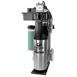
A successful robotic welding operation depends on the ability to maintain high levels of quality and productivity, while also keeping costs low. Unplanned downtime associated with consumable or equipment problems jeopardizes these goals. It can also increase the labor needed for troubleshooting and resolving issues.
But above all else, the weld cell needs to be a safe place for welding operators to work and interact with one another and the robotic welding system.
Peripherals, such as welding reamers (also called nozzle cleaning stations), can help companies achieve their goals, while also helping maintain safety.
This article was published in the August issue of The Fabricator. Read the full article here.
AccuLock Consumables Save Time and Money in MIG Consumable Changeover
AccuLock™ Consumables Save Time and Money in MIG Consumable Changeover
Estimated reading time: 5 minutes
They may seem like small pieces of a welding operation but when consumables aren’t properly installed or maintained, big problems can result — from poor wire feeding to weld quality issues. Related troubleshooting and rework cause costly downtime and lost productivity.
Consumable changeover can also be a time-consuming part of the welding process, especially if it’s necessary to do it frequently or if less experienced welders install consumables incorrectly.
Choosing the right consumables can help reduce or eliminate these hassles. Learn how AccuLock consumables can be used for Bernard® BTB MIG guns and Tregaskiss® fixed automatic and robotic MIG guns to help operations save time and money and improve efficiency.
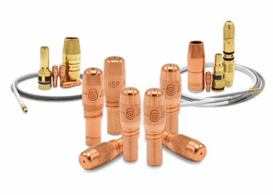
Although small in size, both AccuLock R and AccuLock S consumables can deliver sizable time- and cost-saving benefits by reducing troubleshooting and downtime in industrial welding applications.
The benefits of AccuLock consumables
AccuLock consumables are designed to address common challenges faced in both semi-automatic and automated MIG welding operations. A switch to AccuLock consumables can help operations:
- Increase consumable life while reducing costs and improving productivity.
- Reduce consumable replacement errors and the time and money spent on troubleshooting, rework and downtime.
- Simplify consumables replacement, improving accuracy and reducing employee training.
The AccuLock consumable family for industrial welding applications includes AccuLock R and AccuLock S systems, two options that are designed to deliver timesaving benefits and optimized performance in automated and semi-automatic welding applications.
Load and lock for increased productivity and throughput
The AccuLock S (Semi-automatic) consumables system features liners designed to resolve issues and errors with liner trimming and installation as well as erratic wire feeding problems. Because AccuLock S liners are locked and concentrically aligned to both the contact tip and the power pin, they offer a flawless wire-feed path and error-proof liner replacement every time. In addition, a steel retaining ring on the diffuser helps keep the threaded nozzle in place during use and cleaning.
The AccuLock R (Robotic) consumables system offers front-loading QUICK LOAD® liners that require less than half the time and effort to replace compared to conventional liners and can be changed from a safe zone in a robotic weld cell. Upgrading to AccuLock HDP contact tips can extend life by 10 times or more in pulsed welding applications. In addition, operations currently using TOUGH LOCK® consumables in robotic and fixed automatic MIG guns can easily upgrade to AccuLock R consumables without affecting TCP or requiring programming changes.
Choose according to your needs
When deciding between the two types of AccuLock consumables for industrial welding applications, there are several key factors to consider. It’s important to think about the type of welding being done in the operation and what current issues or challenges need addressing.

AccuLock S consumables are best suited for operations with the following issues or characteristics:
- Primarily focused on semi-automatic welding with little to no automation.
- Dealing with decreased productivity due to liner installation errors, burnbacks, bird-nesting and erratic arc.
- Wanting to reduce the time and costs of troubleshooting, downtime and rework.
AccuLock R consumables are best suited for operations with the following issues or characteristics:
- Primarily focused on robotic or fixed automatic welding with few semi-automatic guns.
- Having a complicated and costly consumables inventory that may be the root cause of frequent consumable replacement errors.
- Experiencing issues with contact tip cross-threading and want increased tip life.
Choosing between AccuLock S and AccuLock R on semi-automatic MIG guns
Customers who are currently using TOUGH LOCK consumables on Bernard BTB MIG guns can upgrade their guns with either AccuLock S or AccuLock R consumables. Although AccuLock S consumables offer many benefits specific to semi-automatic welding applications, in some cases it can make more sense for these welding guns to be upgraded to AccuLock R consumables instead. For example, if a complex inventory of MIG gun consumables is the primary root cause of high carrying costs and consumable replacement errors in a given facility, AccuLock R consumables may offer a better ROI.
Switching existing Bernard BTB MIG guns to AccuLock R consumables is an easy change to make, requiring only an AccuLock R diffuser and an AccuLock contact tip — with no need to switch the liner, power pin, power pin cap or nozzle.
Successful welding operations simplify inventory
Both AccuLock S and AccuLock R systems share a common contact tip to simplify inventory management for facilities that choose to use both. AccuLock contact tips last longer due to increased mass and being buried within the diffuser, away from the heat of the weld. Coarse threads work in tandem with a long contact tip tail to concentrically align the tip within the diffuser prior to thread engagement, ensuring quick, accurate replacement without cross-threading.
Getting the most out of MIG gun consumables
AccuLock S consumables solve many of the issues that can be traced to MIG gun liners that have been trimmed to an incorrect length or that pull out of position inside the MIG gun, creating gaps along the wire feed path. They are a good fit in most semi-automatic applications.
In fleets with a lot of automated welding, AccuLock R consumables can extend contact tip lifespan (especially in pulsed welding applications), eliminate contact tip cross-threading issues, alleviate excessive downtime for consumables replacement and limit safety issues related to climbing up to access robots or wire feeders for gun liner changes.
Although small in size, both AccuLock R and AccuLock S consumables can deliver sizable time- and cost-saving benefits by reducing troubleshooting and downtime in industrial welding applications.
Implementing a Robotic Welding System: 5 Common Questions Answered

Implementing a Robotic Welding System: 5 Common Questions Answered
Estimated reading time: 7 minutes
Many manufacturing operations want to improve productivity and weld quality. Robotic welding can often help achieve these goals. But success with a welding robot doesn’t happen by chance. It takes a lot of upfront planning to help minimize the time and money you need later to make improvements or fix issues.
Before getting started, consider how these common questions could impact the way you establish a repeatable and consistent robotic welding operation — and how you can get the most out of it.
A: The filler metal used in a robotic welding system plays a critical role, as it can affect productivity, weld quality and overall costs. When you choose a wire for robotic welding applications, consider two things: the type and the thickness of the material being welded.
Across various industries, solid wire has been the standard for robotic welding. However, metal-cored wire may offer better productivity and higher quality benefits, especially for manufacturers of heavy equipment, automotive exhaust, chassis and wheels. Metal-cored wire not only allows for faster travel speeds and higher deposition rates, but it also more effectively controls spatter levels to reduce post-weld cleanup. Last, it offers improved welding through mill scale, which helps eliminate pre-weld grinding.
When in doubt, you can get suggestions from experienced welding equipment and filler metal manufacturers to help you match a welding wire to your process needs.
A: Performance in a robotic weld cell is significantly affected by your choice of robotic welding gun and consumables, including the nozzle, contact tip and liner. The right combination of gun and consumables can reduce unplanned downtime, increase lifespan and improve overall equipment effectiveness (OEE) in your weld cell.
There are three types of robotic guns to choose from, depending on your duty cycle and amperage ratings: air-cooled, water-cooled and hybrid. It’s possible for air-cooled guns to reach ratings of 350 to 385 amps at 100% duty cycle with mixed gases. Guns with this rating are well-suited for a variety of applications and help eliminate the need for water-cooled guns, which can be more complex and expensive to maintain. However, hybrid air/water-cooled designs incorporate water cooling on the front of the neck with an air-cooled cable. This design is good for applications with borderline air-cooled duty cycles that experience a higher frequency of consumable changeover. The hybrid gun is the best option to provide an additional rating boost while effectively cooling the consumables, leading to longer lifespans.
Robotic welding systems typically operate at higher duty cycles (compared to semi-automatic welding) and may use transfer modes that can be harsh on consumables. Consider using heavy-duty copper or chrome zirconium contact tips or high-quality tips designed specifically for pulsed welding. Chrome zirconium contact tips resist physical wear (or the keyholing effect) better than copper tips and are ideal for applications with long welds. Make sure to undersize the contact tip from the wire size when using 500-pound-plus wire drums to help ensure consistent wire contact with the tip due to the wire cast. Keep the tips on par with the wire size in small wire packaging.
Nozzle material also plays a factor in the application. Brass nozzles are stronger and have a lower spatter adhesion compared with copper, but brass is more brittle at higher temperatures. In short, brass handles spatter best while copper best handles higher heat.
Choosing a quality liner pays dividends in reducing your unplanned downtime. The majority of time, burnback in contact tips is a direct result of poor wire feeding or a liner cut too short. An accurately trimmed, quality liner will help to consistently improve wire feeding by reducing drag. The result is longer-lasting contact tips and improved robot uptime.
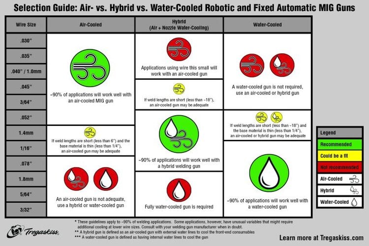
A: Several factors, such as material type, wire size and material thickness, influence the proper weld settings for an application. Some welding power sources have the ability to suggest recommended parameters based on the operator’s input for the application.
When a machine doesn’t have this technology, finding the correct parameters can involve some trial and error on your part to dial in heat and penetration. Consult with the robot manufacturer, welding power source manufacturer or system integrator. These partners can offer expertise and assist in choosing and testing specific materials to establish the proper weld parameters.
A: Establishing an accurate tool center point provides consistency and repeatability across parts and is vital for your system to maintain quality welds.
You can set your own standards for the acceptable amount of TCP drift based on the application and type of welds being made. To set the tolerance of TCP variation, an acceptable starting point can be half of the thickness of the wire diameter. Also keep in mind that your TCP correlates with your contact tip wear — the more key-holed a tip, the more off location your TCP will be.
Touch-sensing features that monitor TCP and track any shifts from the original setting are available on many robotic systems today. If a gun is out of acceptable TCP range, you can remove the neck and recalibrate it to the original specifications with a neck-straightening fixture. TCP can also be automatically adjusted internally by the robot on some systems.
It’s a good idea to schedule regular TCP checks. For example, it can be done every weld cycle, at the end of every shift or when the gun goes through a reamer cycle. The frequency of TCP checks is a matter of your priority preference. While it can be time-consuming to check after every shift, in the long run it can save money by avoiding rework if problems are caught early.
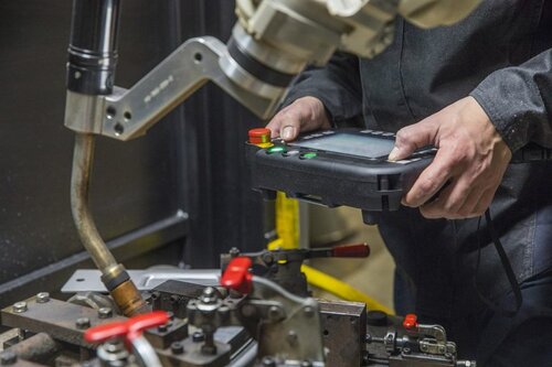
A: Much like programming the weld settings, programming the robot path may also involve some trial and error. When you initially program the robot’s path, think about four factors: the application, the material type, the welding process you are using and the gap size being filled. The travel angle — and whether it’s a push or pull weld — will impact the weld quality and aesthetic. Dialing in the correct path to achieve your desired results can take time.
Having the robot move to perch points or ready-to-enter points once the home positions are set helps to keep the robot safely away from potential collision areas. It also allows the system to move with air-cut moves to and from these points quickly and effectively.
When you program the robot to move to a weld, it’s common to set the approach point just above the weld start location. The robot should approach the start location at a slower and safer speed before it strikes an arc. This approach position provides a good lead-in and typically does not require adjustment unless the weld is relocated. Some robotic systems have technology that assists in setting the initial robot path.
The robot’s welding location can play a role in premature gun failures. Heavy articulation in the gun or an excess of +/-90 degrees, especially during welding, can cause accelerated cable failures. Minimizing your robot’s axis five and six during welding can help extend gun life by reducing wear.
Tips for robotic weld cells
Many variables, including proper cable and consumables selection and TCP control, play an important role in weld quality and gaining successful results with a robotic welding system. Establishing a thorough plan before implementation and continuing to monitor key issues can help you optimize your OEE so you can get the most out of your investment.
From Semi-Automatic to Automatic: Tips for Selecting a Welding Gun

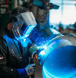
From Semi-Automatic to Automatic: Tips for Selecting a Welding Gun
Choosing the right equipment for a welding operation is critical to achieving high weld quality and productivity while also eliminating costly downtime. And that includes welding guns.
In many cases, companies may have a mix of welding processes and guns. For example, in heavy equipment and general manufacturing, it’s common to have semi-automatic welding along with robotic welding. In oil and gas and shipbuilding applications, semi-automatic welding and fixed automation are prevalent. The combination of welding processes and equipment allows companies serving these industries to weld a variety of part volumes and sizes.
These process mixes, however, can pose challenges in terms of gun selection. That’s why it’s important to know the best welding gun features to look for to achieve the desired weld results — and the best efficiencies.
This article has been published as a web-exclusive on thefabricator.com. To read the entire story, please click here.
Selecting Contact Tips for Robotic Welding

Selecting Contact Tips for Robotic Welding
Contact tips are often referred to as the smallest fuse in the fuse box that is your robotic welding cell. But this small fuse can have a big impact on productivity. In terms of overall efficiency, the contact tip is key.
Contact tips depend upon repeatability to be effective in the welding process. Learn more about the different types of available — and how choosing the right one for your application can improve results and save money.
How do contact tips affect efficiency?
The job of the contact tip is to transfer the welding current to the arc and guide the welding wire as consistently as possible. If either of these two factors degrade, the overall welding process also degrades, affecting quality.
When an operation changes contact tips every few hours, there is an obvious effect on productivity. It requires the weld cell to be shut down, and the operator may have to enter the cell to change out the tip. If the robot is buried inside the welding line, contact tip changeover takes even longer.
Not only are these changeovers inefficient, but they also introduce the potential for mistakes. Every time a human interacts with the robot, there’s a risk of incorrect consumable installation or other improper adjustments that can lead to poor quality welds and costly rework.
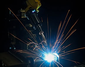
fuse in the fuse box that is your robotic
welding cell. But this small fuse can have
a big impact on productivity.
Choosing the right tip depends on the results you’re looking for and the needs of the application. In the automotive industry, for example, choosing a quality contact tip is critical since unplanned downtime is the enemy of a high-volume multi-robot operation. Contact tips in these applications need more wear resistance.
A high-quality contact tip provides a longer life and a more consistent and stable arc. Longer tip life results in more robot uptime, less time wasted on non-value-added labor for tip changeovers and reduced human interaction with the robot that could lead to error. But the contact tip itself isn’t the only factor impacting tip life — the welding wire, part fit-up, robot programming and grounding also contribute.
Types of contact tips
There are several types of contact tips available. Understanding the differences can help you select the best choice for your operation.
1. Copper contact tips: Contact tips made from this material are the most conductive to transfer welding current. But copper is also the softest option and will keyhole (or wear the bore unevenly) much faster. If keyholing is a pain point in your operation, this may not be the best choice. The initial cost of copper contact tips tends to be cheaper than other options.
2. Chrome-zirconium contact tips: This alloy provides better wear resistance and longer life than copper tips, holding up better to the demands and increased arc-on time of robotic welding. They are slightly less conductive than copper tips, but they are still sufficient for most robotic applications.
3. HDP contact tips: HDP tips can last 10 times longer than copper tips — and up to 30 times in some cases — depending on the application and waveform being used. Operations may be able to go from changing contact tips every two hours to only changing tips once a week. HDP contact tips are engineered to endure wear better, providing increased resistance to arc erosion in pulsed welding, as well as spray transfer and CV MIG. The precise fit between the tip and the wire also results in good arc stability to help produce high-quality welds. Because HDP contact tips reduce the impact of the welding current decline over time, they can provide a more stable and consistent arc over the life of each contact tip. These tips work best in applications that use high-quality copper-coated solid wire.
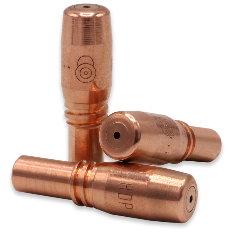
Common pitfalls with contact tips
Once you understand the types of contact tips available, there are numerous factors to consider when choosing the right tip for your application. Here are some common mistakes operations make when choosing contact tips so you can avoid the same pitfalls:
1. Only considering price: Many operations may look only at the price per tip when they purchase contact tips. But it’s important to look beyond the initial price and consider the big picture, which includes the downtime and labor required for changeover, along with any quality issues that may be happening in the weld cell. If a contact tip lasts three times as long, the robot can continue to weld instead of being down for a tip changeover — and there is less human interaction inside the cell .
2. Ignoring ID tolerance issues: The size and cast of the welding wire are important in making a decision about contact tips. Some tips need to be undersized for the welding wire used, while some tips need to match the wire size. And the same exact wire will vary in the necessary contact tip size depending on if the wire comes in a small spool or a 1,000-pound barrel. For most copper and chrome-zirconium tips, it’s recommended to undersize the contact tip by a single wire size when using a 500-pound barrel or greater of wire due to the wire cast. With smaller sizes of wire packaging, use contact tips that match the wire size. The goal is to maintain a clean, consistent contact between the wire and the tip so the weld current is conducted as efficiently as possible.
3. Using poor quality wire: In most cases, poor quality welding wire will lead to poor results from your contact tips. This is due to the lubrication on the wire, as well as the consistency of the wire diameter; inconsistent wire diameter wears the tip faster. Choosing a higher quality wire can improve tip life and produce better results. Also, be aware that wires without a copper coating and cored wires wear tips much faster. Using copper-coated solid wires typically slows contact tip wear.
4. Not being open to change: Some companies think the status quo is fine because they aren’t experiencing issues. They change tips in the robotic welding cell every couple of hours, even if those tips don’t need to be changed. Looking at the true length of their current tips or investing in higher-quality tips could optimize efficiency and the overall process — saving unplanned downtime and reducing the need for non-value-added labor hours.
Analyzing the robotic operation
If contact tips are being removed proactively even when there is no keyholing, burnbacks or erratic arcs, there could be potential to get more life out of contact tips.
So how can companies best analyze their robotic welding operation to determine when to change to a different type of contact tip?
Contact tips react differently to different applications, so an important first step is to run trials with varying quality levels of tips. This will provide an accurate comparison and a level set for expectations. Run each tip to failure, including the current brand, rather than proactively changing the tip on a set schedule. Be sure to log the time each part lasted. Ideally, run multiple contact tips in any trial to eliminate any outliers.
This type of trial can help to identify how much labor time is spent on tip changeovers, how much robot uptime can be achieved and what failures are occurring with each type of contact tip.
If an operation previously experienced 10 burnbacks a day and reduces that to zero by using a higher quality contact tip, this can help eliminate unplanned downtime.
Optimizing contact tip efficiency in robotic welding
It’s important to look beyond the purchase cost and consider the big picture to best evaluate the potential productivity, as well as weld quality and efficiency gains of certain contact tips. The benefits can be especially significant in robotic welding applications, where regular contact tip changeovers can be greatly reduced.
How Robotic Welding Supervisors Can Improve the Operation

How Robotic Welding Supervisors Can Improve the Operation
Gaining a good return on investment (ROI) from a robotic welding system doesn’t happen by chance. It’s a matter of optimizing the robot and the robotic welding cell to operate at peak efficiency. And while this task is a team effort, it is led by the robotic welding supervisor.
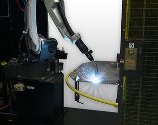
So, what can the supervisor do to guide the way, while looking at more advanced considerations? Pay close attention and collaborate.
Find opportunities for improvement
Even if a robotic welding system is meeting production and quality requirements, it’s important that robotic welding supervisors commit to a continuous improvement process. Regularly looking for ways to increase efficiencies could provide the ability to produce more parts. It can also help identify issues within the robotic welding cell before they become problematic and cause downtime.
Robotic supervisors should pay close attention to details such as cable and consumable management, parts handling and workflow to pinpoint areas that could be streamlined. The goal is to avoid settling for less than optimal work practices to realize the full potential of the system. Doing so can provide companies with higher productivity and profitability and can set them apart from their competitors.
Rely on available resources
While the robotic welding supervisor may oversee the overall health of a robotic welding cell, the robot operator works hands on with the system daily to load and unload parts. For this reason, they are an excellent resource to rely on for insight into potential or existing problems, such as:
• Excessive spatter
• Poor joint configurations, or
• The need for tooling adjustments
Quality technicians are another internal resource to help the robotic welding supervisor identify any issues and drive performance improvements. In conjunction with welding engineers, they can help rectify issues like overwelding or part distortion.
External sources, such as a robotic welding integrator or equipment manufacturer, can help troubleshoot and offer advice to gain efficiencies. In many cases, they can also offer ongoing training that helps everyone improve their interaction with the robotic welding cell.
This article is the second in a two-part series focused on key information welding supervisors should know to help ensure robotic welding success. Read article one, Best Practices for Robotic Welding Supervisors.
Best Practices for Robotic Welding Supervisors

Best Practices for Robotic Welding Supervisors
With careful planning and attention to detail, companies that invest in a robotic welding system can gain advantages, such as:
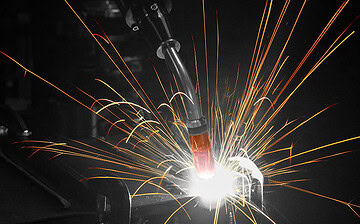
• Increased productivity
• High weld quality
• Cost saving
• Parts consistency
The welding supervisor managing the robotic welding cell plays a key role in achieving these results — and with some best practices in mind, can help ensure long-term success. There are some basics that provide a good starting point.
Understand the robotic welding system
To maximize uptime in a robotic welding system, welding supervisors need to look beyond the administrative and operational duties often involved with this position and consider the actual components in the system. Maintenance personnel can often help.
It’s important for welding supervisors to understand how to quickly troubleshoot issues and how to adjust the weld programs, as needed.
Having a solid understanding of the functions of the robotic welding gun, welding consumables, power cables, and their impact on quality and productivity is also important. It makes it easier to identify problems and provide the best solution.
Establish documentation and maintenance
Keeping an accurate, detailed log of all activities in a robotic welding cell can help welding supervisors maintain control over changes that could impact performance of the robotic welding system. Information to document includes:
• The names of all employees who enter the weld cell, when they entered and why
• Parts that have been cleaned
• Consumable changes
• Drive roll tension adjustments
• Installation of a new welding wire drum
This documentation provides insight into changes in the robotic weld cell, making it easier for maintenance staff to troubleshoot any issues. It can also help the welding supervisor and maintenance personnel determine the appropriate frequency for a preventive maintenance schedule, which helps reduce unexpected downtime.
This article is the first in a two-part series focused on key information welding supervisors should know to help ensure robotic welding success. Read article two, How Robotic Welding Supervisors Can Improve the Operation.
Understanding Fixed Automatic Welding Guns

Understanding Fixed Automatic Welding Guns
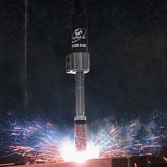
When it comes to automating the welding process, many companies opt for robotic welding systems due to the flexibility they provide and their ability to reach and weld multiple joints. These systems provide the advantages of speed and accuracy and can be reprogrammed to manage new projects.
But these robotic systems aren’t right for every application. In industries such as oil and gas, railcar, structural steel fabrication and shipbuilding, joint configurations are often less complex, consisting of a single part to be welded as opposed to full assemblies. In this case, fixed automatic welding is generally preferred.
About fixed automation welding
Fixed automation welding, sometimes called hard automation welding, is commonly used for welding pipes, structural beams, tanks and vessels in a shop environment prior to them being moved to the jobsite where they will be placed into service. It can also be used for welding steel plates for the general fabrication industry or in the manufacturing of hot water heaters and propane tanks.
Common Factors for Suitable Applications
One common factor in these applications is the need for either longitudinal or circular (inside or outside diameter) welds that require repeatability as opposed to versatility. Other factors that make applications suitable for fixed automation welding include:
1. A high volume of similar parts with low variety
2. Large parts with very long welds or several similar welds
3. Large parts that would be difficult to weld manually
In some cases, fixed automation welding can help companies meet high production goals at relatively low cost. And it is easy for a single operator to oversee and load parts, making it desirable from a labor perspective — particularly given the shortage of skilled welders the industry is facing.
Setups
A fixed automation welding cell can be set up in two ways. The first option requires tooling that holds the part in place, while a fixed automatic gun moves along the weld joint by way of a mechanized seam welder or a track and carriage that holds the gun in place. This option would be viable for a long structural beam, for example.
In the second scenario, the welding gun may be fixed in a single place by tooling while the part, such as a pipe, rotates on a lathe or circumferential fixture during the welding process. In today’s marketplace, there is equipment that can rotate parts in a wide range of diameters and weights.
Tooling for fixed automation welding offers minimal flexibility and can be expensive to adjust for new parts. This is true particularly in comparison to a robotic welding system that can be reprogrammed to articulate and weld in different positions along the X, Y and Z axes.
When investing in the tooling for fixed automation welding, it’s important for companies to determine upfront what their long-term applications will be. Will they continue to weld parts that are straight or circular for the foreseeable future?
Avoiding pitfalls in the process
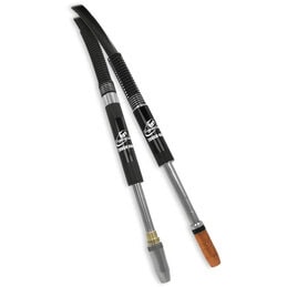
One very important part of the fixed automation welding system is the welding gun. It is not uncommon for companies to take a do-it-yourself (DIY) approach to this piece of equipment. Namely fixturing a semi-automatic gun in place with various components to mimic the performance of a fixed automatic gun. Sometimes this is done out of convenience, due to the shop having an abundance of semi-automatic guns, or because of a perceived cost savings.
Unfortunately, a DIY gun assembly for this process can be time-consuming to set up and maintain, which adversely affects productivity. It also is not optimized for fixed automation welding. Quality may suffer due to off-seam welds or other inconsistencies, leading to rework that further reduces throughput and increases costs. Also, if replacement parts are needed there could be variations in the assembly since it is not set up for this process. Again, this can lead to quality issues.
Instead, it is important to invest in a fixed automatic gun that is designed for the process. These guns have consistent components that can be sourced from manufacturers so that the welds are repeatable. And the gun manufacturers can provide service and technical support.
Looking at the choices
Guns need to be specified or customized for the application according to the available space, taking into account the distance between the gun and the part and also how far away the wire feeder is. These factors impact neck length and bend or angle, as well as cable choices.
Necks
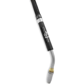
Necks are typically available in the marketplace in varying lengths, from approximately 4 to 12 inches. Available with either a straight neck or 22-, 45- and 60-degree bends. Companies need to determine the reach required to meet the weld joint, as well as the necessary angle for completing a sound weld.
Cable Lengths
Cable lengths vary from as short as 3 feet to as long as 25 feet. Longer cables are ideal for reaching a wire feeder placed further away from the part, including on a boom. In other situations, a company may mount the feeder directly on the tooling or nearby. In that case, a cableless gun is an option for air-cooled operations. These guns plug directly into the wire feeder via a power pin and do not require a cable. Amperage and duty cycle also need to be factored into the selection of a fixed automatic gun, and both depend on the thickness of the material being welded and the amount of arc-on time required.
Air-cooled fixed automatic guns are typically available from 300 to 500 amperage models, offering either 60% or 100% duty cycle. Duty cycle is defined by the amount of time within a 10-minute cycle the gun can weld without becoming overly heated.
The necks on these guns are particularly durable since they have fewer internal channels than a water-cooled gun and rely on the ambient air to cool them. They are also more resistant to bending, and replacement parts are less expensive.
For higher-amperage fixed automation welding applications that require longer periods of welding on thicker material, a water-cooled gun may be a better choice. These models are typically available in amperages ranging from 450 to 600 amps and offering 100% duty cycle.
Hybrid water-cooled guns are another option. These fixed automatic guns have a sturdy neck similar to an air-cooled model with water channels running external to it. These channels make the guns easier to maintain than water-cooled guns.
Additional considerations
Along with selecting the appropriate components for a fixed automatic gun, it’s also essential to choose high-quality consumables — nozzles, contact tips and gas diffusers. This helps minimize downtime for frequent changeovers and supports production goals. They can also reduce quality issues that could require rework later in the welding operation.
Consumables are available that can be used across different types of welding guns, including semi-automatic ones and fixed automatic guns. This compatibility can be beneficial to simplifying inventory and preventing errors when installing new consumables on either type of gun.