What is a MIG Gun Consumable?

Welding gun consumables can be an overlooked part of the MIG welding system. As small components of a MIG welding gun, many users simply use whatever consumables come installed or are the least expensive to purchase. However, spending the time to carefully select, store, install, and maintain your gun consumables can pay off in terms of reduced costs, increased productivity and better weld quality.
Read on to learn everything you need to know about MIG welding consumables including tips, videos, product recommendations and more!
Welding Gun Consumable Components
MIG gun consumables are the parts of the welding gun that wear with use and require ongoing replacement to ensure consistent weld quality. Consumable systems are comprised of the following components:
- Nozzle / gas cup
- Contact tip
- Gas Diffuser / retaining head
- Liner / conduit
- Power pin
It should be noted that only some MIG guns include the power pin as part of the consumable system. In these systems, the entire wire delivery path from the welding machine to the weld puddle has been fully optimized from a consumables perspective.
Nozzles (also known as Gas Cups)
Nozzles direct the flow of the shielding gas to the weld puddle. In any welding application, the right material, shape and style of nozzle can have an impact on quality, productivity, and the cost of the welding operation.
Nozzle Materials
Brass

Copper

Plated Copper


Nozzle Shapes
The best choice is to use as long and large of a nozzle as possible that still allows access to the weld joint. One exception to this rule is when heavy spatter is expected (galvanized base metal, oily surface, short circuit well, 100% CO2, etc.) – in this case try a short nozzle with a larger bore size. Maximizing the nozzle size vs weld access helps ensure the greatest shielding gas flow and also helps prevent sticking the contact tip to the workpiece or table in manual welding applications. Larger nozzles are also less prone to collecting spatter compared to those with smaller inside diameters.
Straight
Tapered
Bottleneck
Nozzle Connection Styles
Nozzles for MIG welding guns are available in several connection styles:
Slip-on
Thread-On
Two-Piece

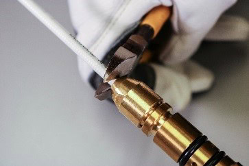
Contact Tips
Contact tips are responsible for transferring the weld power to the wire as it passes through to create the arc. This means that its connection with the gas diffuser is critical to ensure good electrical conductivity. A tapered connection is preferred for this reason since it helps to hold the tip securely and accurately in position. The material, size and style of the contact tip also have a role to play in how it performs in any given welding application.
Contact Tip Materials

- Copper contact tips are the most common and are suitable for most MIG welding applications.
- Chrome zirconium contact tips are used in more demanding welding applications. As a general rule of thumb, they last approximately twice as long as copper tips.
- HDP contact tips have an insert at the front of the tip that is comprised of a special alloy that resists both mechanical and electrical wear. This allows them to last 6-10x longer than copper and chrome zirconium contact tips and are ideal for pulsed welding applications.
Contact Tip Sizes
Both the outside size and shape and the inside diameter of the contact tip can impact its performance:
Outside Diameter Considerations
Inside Diameter Considerations
Contact Tip Styles

Threaded contact tips screw into the diffuser and should be tightened into place with a tool. Look for coarse threads that speed replacement.

Drop-in contact tips are threadless and are usually held in place by the nozzle or other consumable parts. They do not require the use of tools for installation.
Gas Diffusers (also known as Retaining Heads)

Gas diffusers are designed to conduct electricity to the contact tip while distributing the shielding gas. Mechanically, they also hold the contact tip and nozzle in place on the gun’s neck.
A poorly designed diffuser might:
- Have gas holes that clog frequently, or are not reachable by nozzle cleaning station cutter blades, leading to porosity
- Channel the shielding gas improperly resulting in turbulent gas flow and unbalanced gas coverage
- Allow connections with the tip, nozzle or neck to loosen frequently resulting in high electrical resistance and additional heat
Liners (also known as Conduit)
The liner’s job in MIG welding is to guide the welding wire from the welding machine and/or wire feeder, through the gun cable and through the contact tip. Choosing the right size, type, material, and quality of liner and then installing it correctly is necessary for good welding performance.
Types of liners
- Conventional liners are replaced from the back of the MIG gun and are the most common type of gun liner used today.
- Front-loading liners load from the front of the MIG gun without disturbing the wire or wire feeder connection. They can be replaced in half the time it takes to replace a conventional liner. These are ideal for MIG guns used in robotic or boom-mounted applications.
- Jump liners – Part of a three piece system, a short liner (jump liner) is used through the neck of the gun where most of the internal wear occurs. An adapter joins this short front liner to the longer rear liner. A jump liner is ideal for welders who frequently change their gun necks, run nylon liners (for aluminum wire) or utilize a wire brake (automated applications requiring touch sensing).
- Dual-locked liners – these liners are locked in place at the front and back of the welding gun to prevent gaps and misalignments along the wire feed path.
Power Pins

Power pins provide a direct connection for wire, weld power and gas flow between the welding machine and/or wire feeder and the MIG gun. The power pin also determines a MIG gun’s compatibility with a given welding machine. An accurate gun to machine connection is critical to ensure that the welding wire (also known as filler metal), gas and weld power are passed efficiently to the MIG gun.
Power pins are generally very durable and are the most infrequently replaced consumable part due to wear. However, a welder may choose to replace their power pin with a different one so that they can use a single gun on different machines.
Similarly, a company with more than one brand of welding machine could configure their gun fleet with different power pins allowing them to consolidate their MIG gun and consumables inventory. The related benefits include:
A few additional points to understand:
Selecting Welding Gun Consumables: Which Ones Are Right For You?
MIG gun consumables must be carefully selected to meet the needs of your welding applications and your overall business. Many variables should be taken into consideration when making your selections. Here are a few questions to consider:
Shape and Size
Material

Connection Style
Positioning

Liner Type
Have you considered all the liner options out there to ensure you have the right one for your operation?
Inventory
If you have many welding guns, using as many common consumables parts as possible can ease employee training requirements, help to prevent replacement errors, and reduce inventory carrying costs.


Storing, Installing and Maintaining MIG Welding Gun Consumables
For MIG consumables, several pitfalls exist that can shorten their lifespan. Taking the time to learn tips for properly storing, installing and maintaining them can positively affect productivity, quality, and the bottom line.
Storing MIG Gun Consumables
Installing MIG Gun Consumables

Maintaining MIG Gun Consumables

Solving Issues with MIG Welding Gun Consumables
Although they are not always the root cause of welding issues, MIG gun consumables are often the first to be checked or replaced during troubleshooting due to their low cost and ease of access. The following welding issues may be addressed via MIG gun consumables (items in italics are additional potential root causes that are NOT related to gun consumables):

- Contact Tip Burnback
This failure mode occurs when the welding wire melts back into the contact tip interior blocking feeding. Possible root causes include:- Liner trimmed incorrectly can lead to gaps and friction at liner junctions and debris buildup in liner / contact tip
- Contact tip too small for the wire
- Improper tip stickout
- Erratic wire feeding
- Loose connections (tip / diffuser / neck)
- Improper wire stickout
- Improper voltage and/or wire feed speed
- Faulty ground
- Wire Does Not Feed / Erratic Wire Feeding
This is when the filler metal will not move backward or forward or it moves inconsistently.- Liner trimmed incorrectly can lead to gaps and friction at liner junctions and debris buildup in liner / contact tip
- Wrong size contact tip
- Worn or dirty contact tip
- Contact tip burnback
- Wrong size liner
- Bird nest
- Feeder / relay malfunction
- Poor adaptor connection
- Worn or broken switch
- Improper drive roll size
- Drive roll tension misadjusted
- Worn drive roll
- Improper guide tube relationship
- Improper wire guide diameter

- Short Contact Tip Life
Burning through more contact tips per shift than usual can be a sign of one of these problems:- Liner trimmed incorrectly can lead to gaps and friction at liner junctions – this can misalign the wire inside contact tip leading to contact tip keyholing
- Improper contact tip stickout position (stick-out vs. flush vs. recess)
- Improper contact tip duty or material for application
- Contact tip burnback
- Erratic wire feeding
- Improper wire stickout
- Improper voltage and/or wire feed speed
- Faulty ground
- Poor quality welding wire
- Short Nozzle Life
Frequently replacing nozzles can be a sign of underlying issues. These include:- Nozzle is undersized for the application
- Nozzle loose or deformed due to being used as a chipping hammer
- Tapered and bottleneck shaped nozzles have an increased risk of spatter build-up due to the narrower bore which can shorten life
- Incorrect contact tip recess can lead to erratic arc and increased spatter shortening life
- Erratic Arc
Erratic arc can be heard and felt when welding by hand. There will be excessive popping and crackling sounds from the arc and vibrations can be felt in the gun caused by wire chatter.- Liner trimmed incorrectly can lead to gaps and friction at liner junctions
- Buildup inside the liner
- Wrong size contact tip
- Worn contact tip
- Not enough bend in gun’s neck

- Extreme Spatter
Generating more spatter than usual can be caused by:- Incorrect contact tip recess can lead to erratic arc and increased spatter
- Poor / loose consumables connections
- Improper machine parameters
- Improper gas shielding
- Contaminated wire or work piece
- Poor / loose ground connections

- Porosity in Weld
Small holes throughout the weld bead is called porosity. This can be caused by:- Nozzle insulator worn
- Nozzle plugged
- Gas diffuser damaged
- Gas diffuser gas holes plugged
- Worn, cut or missing o-rings
- Consumables are under-sized for the application
- Travel speed too fast
- Poor position / approach angle
- Bay doors open / breeze blowing through shop
- Faulty solenoid
- No shielding gas
- Flow improperly set
- Ruptured gas hose
- Control circuit loss
- Loose fittings

- Birdnesting
Welding wire may accumulate inside the welding machine or inside the welding gun resembling a bird’s nest.- Liner trimmed incorrectly can lead to gaps and friction at liner junctions
- Buildup of debris in liner
- Wrong liner size
- Contact tip burnback
- Wrong contact tip size
- Wrong power pin
- Power pin / feeder misalignment
- Incorrect drive roll size or style
- Incorrect drive roll tension settings
- Worn drive rolls
Surprised by how many welding issues are caused by improperly trimmed liners? Read below to learn more about why liner trim length is so critical to MIG welding success.
Need potential solutions for the above issues? View our Welding Troubleshooting Guide.

