Pulsed Welding and Through-Arm Robots: What to Know
Estimated reading time: 6 minutes
After early adoption by the automotive industry, the combination of pulsed gas metal arc welding (GMAW) and through-arm robots has become a more common part of automated welding operations in general manufacturing and fabrication. In fact, through-arm robots have largely replaced conventional ones in the last decade as more robot OEMs lean toward that design.
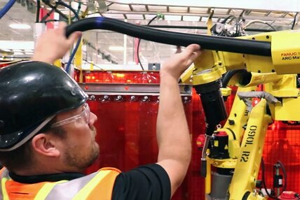
Pairing this type of robot with pulsed MIG welding can help companies improve productivity and quality. Through-arm robots, as their name implies, feature a hollow upper-arm casting that allows the welding power cable to run through the center. This design eliminates the need for the cumbersome cable management usually associated with conventional robots. Routing the cables through the arm also prevents them from getting caught on tooling or parts. The design improves joint access by reducing the overall size and shape of the robotic welding gun (i.e., end-of-arm tooling). Pulsed welding enhances the benefits of this combination by helping lessen part distortion, minimizing burn-through — especially in instances when the robot’s tool center point (TCP) is off — and reducing spatter.
The pulsed welding waveforms, however, can create wear on the through-arm robot’s welding gun components, such as welding consumables and welding power cables. Companies need to consider several factors during their selection and operation to gain consistent results and help these components last.
Understanding the impact of pulsed waveforms
Pulsed welding works well for lap joints on thinner materials, which is why it is prevalent in the automotive industry. Galvanized steel used for vehicle body skins, for example, may be as thin as 0.7 millimeters. Pulsed welding can also be used for thicker materials, up to and beyond 1/4 inch, with good results.
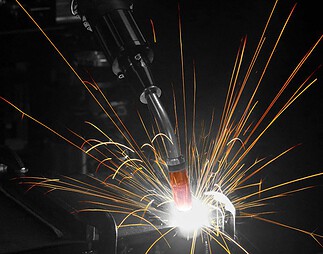
This welding transfer mode operates as a modified spray transfer process and requires a power source with specific pulsing capabilities. During operation, the welding output switches rapidly between high peak and low background currents. The peak current is responsible for pinching off the molten droplet from the filler metal and easing it toward the weld joint. While this is happening, the background current keeps the arc on and stable but is too low to transfer any filler metal. The weld pool cools slightly while the low background cycle occurs.
While pulsed welding offers benefits that support quality, the waveforms also cause a higher level of electrical and thermal stress on the through-arm robot’s welding power cable, since it is confined within the arm of the robot as opposed to being externally routed over the arm. The waveforms can also be harsh on welding consumables — particularly contact tips.
Impact on Contact Tips
The peak amperage values in a pulse waveform can cause micro-arcing inside the contact tip, which leads to higher resistance and ultimately burnback or the fusing of wire inside the bore of the contact tip. Chrome zirconium contact tips are slightly harder than copper tips and resist mechanical wear better in CV applications. However, a pulsed-welding-specific contact tip is needed to combat the electrical wear and micro-arcing and extend tip life in pulsed welding applications.
Impact on Welding Power Cables
Pulsed waveforms can be similarly hard on the welding power cable in a through-arm robot. Variations in welding joint access can put stress on the cable as the robot arm articulates, which can affect the current path. Again, the amperage peaks associated with pulsed waveforms can transfer across any open connections. If electrical resistance is high, the current will travel toward an easier path, leading to damage to the copper within the cable and burnt or shorter liners.
Unfortunately, it is difficult to predict cable failure in a pulsed welding application since there are few indicators. Periodically, the liner may become fused within the welding power cable or become discolored due to the current taking the liner as the path of least resistance as the power cable fails. If any cracks in the power cable jacket or exposed copper appear, it is time to replace the cable.
Ways to combat wear
There are steps companies can take to help minimize wear caused by pulsed waveforms to make through-arm robot components last longer.
1. Use Contact Tips for Pulsed Welding
As mentioned previously, companies can look for contact tips designed specifically for pulsed welding. These are made from materials that better resist electrical stress and also tend to have a tighter inside diameter (ID) in the bore to reduce the opportunity for the welding wire to float. This helps the contact tip conduct electricity much more efficiently and for longer while maintaining a tighter TCP. These contact tips can also help minimize burnback.
2. Check Contact Tip to Work Distance
Paying attention to contact-tip-to-work distance (CTWD) is also important. It needs to be consistent along the entire length of the weld joint. This supports correct parameters in the pulsed welding process and reduces spatter that could shorten the life of the contact tip.
3. Select the Best Welding Power Cable
Welding power cables with a dynamic or sliding electrical connection help ensure electricity can pass through uninhibited even when the cable experiences mechanical stress from the robot’s movements. This improves the ability of the pulsed waveform to transfer current more efficiently. Companies should also select a power cable with reliable, consistent electrical connections and consider replacing the cable annually in high-production environments.
4. Improve the Robot Arm Path
Improving the path of the robot arm, to ease extreme bending and twisting at joints five and six (J5/J6), is another way to minimize power cable wear. There are means to program the through-arm robot so that it can reach the weld joints efficiently without impacting cycle time. Often the movements that companies need to change the most are air moves and wait or clear positions. The key is to use the robot arm in the most neutral position to reduce stress on the welding power cable, which can be done by minimizing the articulation of J5/J6 during welding and/or air movements.
Gaining the best results
In the right application, pulsed welding with a through-arm robot can help companies improve weld quality and productivity. Working with a trusted robot integrator, distributor and/or welding gun manufacturer can help ensure that the proper consumables and welding power cables are in place, as well as assist in programming the robot to provide the most efficient movements.
Republished Welding Journal (August 2022) with permission from the American Welding Society (AWS). Click here to view the original article.