Solving Common Causes of Welding Porosity
Estimated reading time: 7 minutes
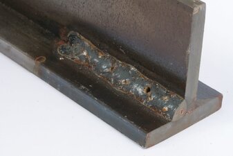
Porosity, cavity-type discontinuities formed by gas entrapment during solidification, is a common but cumbersome defect in MIG welding and one with several causes. It can appear in semi-automatic or robotic applications and requires removal and rework in both cases — leading to downtime and increased costs.
The major cause of porosity in steel welding is nitrogen (N2), which gets involved in the welding pool. When the liquid pool cools down, the solubility of N2 is significantly reduced and N2 comes out of the molten steel, forming bubbles (pores). In galvanized/galvanneal welding, evaporated zinc can be stirred into the welding pool, and if there is not enough time to escape before the pool solidifies, it forms porosity. For aluminum welding, all porosity is caused by hydrogen (H2), by the same way as N2 works in steel.
Welding porosity can appear externally or internally (often called sub-surface porosity). It can also develop at a single point on the weld or along the entire length, resulting in weak welds.
Knowing how to identify some key causes of porosity and how to quickly solve them can help improve quality, productivity and the bottom line.
Poor Shielding Gas Coverage
Poor shielding gas coverage is the most common cause of welding porosity, as it allows atmospheric gases (N2 and H2) to contaminate the weld pool. Lack of proper coverage can occur for several reasons, including but not limited to poor shielding gas flow rate, leaks in the gas channel, or too much air flow in the weld cell. Travel speeds that are too fast can also be a culprit.
If an operator suspects poor flow is causing the problem, try adjusting the gas flow meter to ensure the rate is adequate. When using a spray transfer mode, for example, a 35 to 50 cubic feet per hour (cfh) flow should suffice. Welding at higher amperages requires an increase in flow rate, but it’s important not to set the rate too high. This can result in turbulence in some gun designs that disrupts shielding gas coverage.
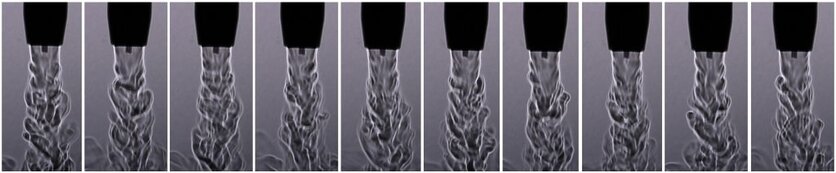
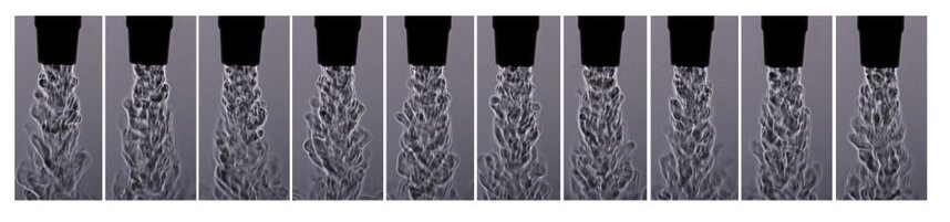
It’s important to note that differently designed guns have different gas flow characteristics (see two examples below). The “sweet spot” of the gas flow rate for the top design is a lot larger than that of the bottom design. This is something a welding engineer needs to consider when setting up the weld cell.
Also check for damage to the gas hose, fittings and connectors, as well as O-rings on the power pin of the MIG welding gun. Replace as necessary.
When using fans to cool operators or parts in a weld cell, take care that they are not pointed directly at the welding area where they could disrupt gas coverage. Place a screen in the weld cell to protect from external air flow.
Re-touch the program in robotic applications to make sure there is a proper tip-to-work distance, which is typically ½ to 3/4 inch, depending on the desired length of the arc.
Lastly, slow travel speeds if the porosity persists or consult a MIG gun supplier for different front-end components with better gas coverag
Base Metal Contamination
Base metal contamination is another reason porosity occurs — from oil and grease to mill scale and rust. Moisture can also encourage this discontinuity, especially in aluminum welding. These types of contaminants typically lead to external porosity that is visible to the operator. Galvanized steel is more prone to subsurface porosity.
To combat external porosity, be certain to thoroughly clean the base material prior to welding and consider using a metal-cored welding wire. This type of wire has higher levels of deoxidizers than solid wire, so it is more tolerant of any remaining contaminants on the base material. Always store these and any other wires in a dry, clean area of similar or slightly higher temperature than the plant. Doing this will help minimize condensation that could introduce moisture into the weld pool and cause porosity. Do not store wires in a cold warehouse or outdoors.
When welding galvanized steel, the zinc vaporizes at a lower temperature than the steel melts, and fast travel speeds tend to make the weld pool freeze quickly. This can trap zinc vapor in the steel, resulting in porosity. Combat this situation by monitoring travel speeds. Again, consider specially designed (flux formula) metal-cored wire that promotes zinc vapor escape from the welding pool.
Clogged and/or Undersized Nozzles
Clogged and/or undersized nozzles can also cause porosity. Welding spatter can build up in the nozzle and on the surface of the contact tip and diffuser leading to restricted shielding gas flow or causing it to become turbulent. Both situations leave the weld pool with inadequate protection.
Compounding this situation is a nozzle that is too small for the application and more prone to greater and faster spatter buildup. Smaller nozzles can provide better joint access, but also obstruct gas flow due to the smaller cross-sectional area allowed for gas flow. Always keep in mind the variable of the contact tip to nozzle stickout (or recess), as this can be another factor that affects shielding gas flow and porosity with your nozzle selection.
With that in mind, make sure the nozzle is large enough for the application. Typically, applications with high welding current using larger wire sizes require a nozzle with larger bore sizes.
In semi-automatic welding applications, periodically check for welding spatter in the nozzle and remove using welder’s pliers (welpers) or replace the nozzle if necessary. During this inspection, confirm that the contact tip is in good shape and that the gas diffuser has clear gas ports. Operators can also use anti-spatter compound, but they must take care not to dip the nozzle into the compound too far or for too long, since excessive amounts of the compound can contaminate the shielding gas and damage the nozzle insulation.
In a robotic welding operation, invest in a nozzle cleaning station or reamer to combat spatter buildup. This peripheral cleans the nozzle and diffuser during routine pauses in production so that it does not affect cycle time. Nozzle cleaning stations are intended to work in conjunction with an anti-spatter sprayer, which applies a thin coat of the compound to the front components. Too much or too little anti-spatter fluid can result in additional porosity. Adding in air blast to a nozzle cleaning process can also aid in clearing loose spatter from the consumables.
Maintaining quality and productivity
By taking care to monitor the welding process and knowing the causes of porosity, it’s relatively simple to implement solutions. Doing so can help ensure greater arc-on time, quality results and more good parts moving through production.