5 Tips for Improving Weld Quality
Estimated reading time: 7 minutes
Establishing consistent levels of weld quality is important for attaining production goals and a better bottom line in semi-automatic welding operations. However, there are many factors that can negatively impact those efforts, including a lack of skilled labor, inadequate or aging equipment or using the wrong welding consumables.
To avoid costly rework associated with poor weld quality, it’s critical to implement proper welder training. Evaluating the welding operation on a regular basis for issues can also help, along with following these key tips.
No. 1: Size contact tips correctly
Welding contact tips are available in a range of diameters — typically 0.023 to 1/8 inches — to accommodate different welding wire sizes. The wire packaging, in part, determines what size contact tip is appropriate to support good weld quality.
Welding wires in larger drums — 500 pounds or more — have a larger cast and are flatter so there is less degree of arc. This means there is less opportunity for the wire to make consistent contact when feeding down the bore of the contact tip, resulting in an erratic arc and weld quality issues. To avoid problems when using copper and chrome zirconium welding contact tips (with Bernard and Tregaskiss consumables), undersize them for the diameter of wire. For example, match an 0.045-inch wire to a 0.039-inch contact tip. For other manufacturers’ contact tips, request recommendations.
Copper and chrome zirconium contact tips can be matched size for size with wire on spools or in drums less than 500 pounds since the wire has a tighter cast.
For AccuLock™ HDP contact tips, the wire and tip size can be matched regardless of the welding wire drum or spool size.
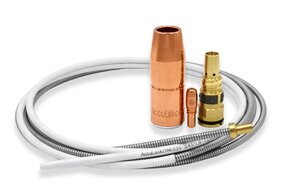
No. 2: Size and change over liners properly
As with contact tips, welding liners are available in various diameters and ranges, from 0.035 to 0.045 inch or from 0.045 to 1/16 inch. To avoid issues like burnback (the fusing of a weld in a contact tip), poor wire feeding and an erratic arc that can be detrimental to weld quality, match the diameter of welding wire to that of the liner. This supports the wire as it feeds through the liner.
It’s equally important to trim the liner properly. A liner that is too short can create wire chatter, an erratic arc and bird-nesting (a tangle of wire in the drive rolls). If the liner is too long, it can cause the wire to weave. Both situations can cause poor welds and, potentially, rework.
Always use the gauge provided by the manufacturer to ensure that the liner is trimmed correctly. The AccuLock S consumable system is also a good option, as it provides error-proof liner replacement. The liner loads through the neck at the front of the gun and is locked and trimmed flush with the power pin at the back of the gun, which eliminates the need to measure.
No. 3: Keep electrical resistance low
Electrical resistance — or interference with the flow of electricity in a semi-automatic MIG gun’s circuit — generates heat and can impede weld quality by negatively impacting the gun’s components. There are several causes that can be rectified to prevent issues such as inconsistent weld appearance or an erratic arc.
Through ongoing use, connections begin to wear and loosen, leading to electrical resistance. Address this problem by tightening connections between the gas diffuser, gun neck and handle, as well as the connections from the power cable to the power pin and wire feeder.
Power cable wear that results in hotspots can also lead to electrical resistance. This wear may not always be visible, so as a course of troubleshooting, operators should consider this problem as a cause of poor weld quality. Replace the cable as necessary to prevent issues. Likewise, increased electrical resistance can occur in the gun handle, since it is an area of high use and bending. Look for signs of wear and replace as needed.
No. 4: Be mindful of cleanliness
There are various aspects of cleaning and weld prep that can help support good weld quality. Always follow proper procedures for cleaning the base material to prevent defects like porosity that can be caused by welding through dirt, oil and debris.
It’s also important to be proactive about cleaning consumables. For example, weld spatter buildup in the nozzle or in the ports in the gas diffuser can hinder shielding gas coverage, which also leads to porosity. Clean or replace these consumables when excessive spatter is evident. Operators can also apply anti-spatter compound to the consumables by dipping the front inch and a half of the nozzle into the liquid. Use the anti-spatter compound sparingly to avoid damaging the nozzle insulator.
Storing consumables in a clean area minimizes the opportunity for dust, oil or other contaminants to adhere to the surface of the welding contact tip, nozzle and diffuser and adversely affect weld quality. A covered container with compartments for each welding consumable is a good option to protect them.
Also consider how to handle the welding liner during changeover. Be careful not to drag the liner on the floor while feeding it into the gun, since doing so can cause debris to collect on it and be pulled into the gun.
No. 5: Plan for inspection and maintenance
Preventative maintenance and ongoing care of the MIG gun and consumables can go far in supporting high weld quality. Set a schedule to inspect, maintain and repair the components.
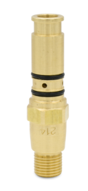
Although often overlooked during regular inspections, the O-rings found throughout the gun are important to assess. If they start to degrade or break, they can cause shielding gas leaks that lead to porosity and potentially extra costs for shielding gas if the operator increases gas flow to compensate for the leak. Check O-rings on the power pin, gas diffuser and liner during routine preventive maintenance and replace these components as needed.
Look for damage to the power cable, such as nicks or tears that can impede gas flow. Visually inspect the gun handle for cracks or missing screws and the trigger for sticking or malfunction. Repair or replace as necessary.
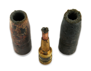
Last, inspect the welding contact tip for keyholing (an oblong wear of the bore); this can cause drifting wire and arc start failures that affect weld quality.
Long-term results
Improving weld quality is a matter of ongoing evaluation. Supervisors and managers overseeing semi-automatic welding operations should regularly consult with welding operators to make sure they are following best practices. Ongoing training and quickly troubleshooting issues can also support good weld quality and prevent costly downtime and rework.