Solving Five Causes of Downtime in a Robotic Welding Operation
Ensuring a robotic welding cell stays productive and consistently generates a positive return on investment is determined, in large part, by the amount of downtime it incurs. Since robotic welding systems are built for speed, accuracy and repeatability, the cost of arc-off time spent addressing issues is exponentially higher than in a typical welding cell. Having welding operators and robotic weld cell supervisors who can quickly troubleshoot and solve problems makes all the difference when it comes to keeping costs down, generating high-quality results and maintaining optimal efficiency.
Here are five common causes of downtime that can occur in a robotic welding operation, along with ways to prevent and address them.
Cause No. 1: Poor cable management and/or incorrect cable selection
If a power cable rubs against the robot, on parts or against tooling, it can prematurely fail and cause unnecessary downtime. In some cases, the cable may even catch on components and wear them out, too.
Cables that are too long or too short create excessive strain by either being pulled too tight or flopping around too much and creating strain at the front housing — both of which lead to premature cable failure. These issues are common with conventional style robots, where the power cable connecting to the robotic MIG gun is external to the robot arm. The goal is to set cable length to allow it to exit the front housing with a smooth arc, resulting in minimal strain.
Alternately, in the case of a through-arm robotic welding system, downtime often occurs due to improper installation of the gun and/or improper cable length.
Solutions:
By adding cable tensioners, which are essentially spring-loaded cable devices that hold the power cable, operators can ensure the cables stay properly supported on a conventional robot. Programming the robot so that it doesn’t accelerate or decelerate too quickly or abruptly can also protect against premature cable failure.
In some cases, if the work envelope is quite small, cable rubbing may be unavoidable. Using a protective wrap to shield the cable from rubbing can help. These are available in the marketplace as either a leather or woven nylon cover, or a plastic spiral wrap.
When installing a through-arm robotic MIG gun, be sure to position the robot with the wrist and top axis at 180 degrees, parallel to each other. Then install the insulating disc and spacer the same as with a conventional over-the-arm robotic MIG gun. Always be sure the power cable position is correct and has the proper “lie” with the robot’s top axis at 180 degrees, and ensure the power cable has about 1.5 inches of slack when installing it, so it is not too taut.
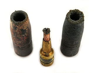
Cause No. 2: Premature consumable failure
Although consumables may seem like a small part of the robotic welding process, they can have a big impact on how productive and effective an operation is. Nozzles, contact tips, retaining heads (or diffusers) and liners can all fail prematurely or perform poorly for a variety of issues, including spatter or debris buildup, loose connections and improper installation. Issues with the contact tip — especially burnbacks and cross-threading — are also relatively common, and are often caused by a liner being trimmed too short.
Solution:
Choosing durable, easy-to-install consumables is key to minimizing both planned and unplanned downtime in a robotic welding operation. Longer lasting consumables require less frequent changeover. Plus, designs that help less experienced welding operators install consumables correctly result in less troubleshooting.
Contact tips with coarse threads and a long tail ensure the tip aligns concentrically in the gas diffuser before the threads engage. These features help minimize the risk of cross-threading. Also, contact tips with greater mass at the front end and that are buried further down in the gas diffuser better withstand heat from the arc to help them last longer.
For pulsed welding operations, contact tips with a hardened insert help the tip last 10 times longer than those made of copper or chrome zirconium. That is important since the pulsed waveforms are especially harsh on contact tips and cause them to wear prematurely.
Operators should always inspect consumables for signs of spatter or debris buildup during routine breaks in production and, if signs of either are present, replace or clean them. They should also ensure their nozzle cleaning station or reamer is working properly, if one is present, and that it is programmed to ream at a rate that is appropriate for that specific application. It may be necessary to increase the frequency of the anti-spatter spray application or reaming throughout the programmed welding cycle.
Check that all consumable connections are clean and secure, as loose connections can generate additional heat through increased electrical resistance, shortening consumable life and/or causing them to perform poorly. Consumable designs that are tapered can also help minimize heat buildup and extend consumable life by offering better electrical conductivity.
Welding operators should always follow the manufacturer’s instructions for liner trimming and installation, as a liner can cause inconsistent feeding if cut too short. It is a good idea to use a liner gauge to confirm the correct liner length. There are also spring-loaded modules that work in conjunction with a front-loading liner to help minimize issues if the liner is cut to an incorrect length. These are housed in the power pin and apply forward pressure on the liner after it is installed. They typically allow up to 1 inch of forgiveness if the liner is too short. It is also important to replace liners frequently enough, as a clogged liner full of debris and dirt will not feed properly, and may cause premature contact tip failure.
Cause No. 3 Excessive spatter buildup in consumables
Excessive spatter buildup in consumables can be caused by a nozzle cleaning station that isn’t operating properly and can easily cause unnecessary downtime. Issues related to nozzle cleaning stations can be caused by an incorrect position between this peripheral and the robotic MIG gun nozzle; poor anti-spatter compound coverage; or a dull or improperly sized cutter blade.
Solution:
If a nozzle cleaning station doesn’t appear to be working properly, first check that the robotic MIG gun is concentric to the cutting blade on the reamer. Misalignment of the nozzle can lead to partial cleaning and excessive spatter buildup.
Also check that the anti-spatter sprayer, if present, is full, correctly positioned and properly coating the nozzle during spraying. The nozzle should be slightly damp on the inside and outside, and covered up to three-quarters of an inch from the bottom of the nozzle. Note that over-spraying anti-spatter compound can cause nozzles to deteriorate prematurely, so it should never be sprayed for more than half a second.
Be sure that the cutter blade matches the diameter of the nozzle bore, so that it can effectively clean during the ream cycle without hitting the nozzle or the gas diffuser. It is also important to have a sharp cutter blade and to make sure that the nozzle is at the correct depth within the jaws of the nozzle cleaning station.
Finally, adding an air blast feature to a robotic GMAW gun can help support the nozzle cleaning station’s overall effectiveness. An air blast feature blows high-pressure air through the gun’s front end, which helps remove spatter, debris and other contaminants. This feature can help reduce how often a nozzle cleaning station needs to be used and, ultimately, boost productivity.
Cause No. 4: Collisions
Collisions can occur as the result of tooling that hasn’t been secured properly, an item inadvertently being left in the weld cell or poor part fit-up. Unfortunately, not only can collisions create unwanted downtime, but they can also damage the robot arm, the robotic MIG gun and/or front-end consumables.
Many newer robots are equipped with collision detection software that serves the same function as a shock sensor, but some companies still use a shock sensor as a backup safety measure.
Solution:
For robots that don’t have built-in collision software, a shock sensor can act as a safety device to protect the robot arm and gun from damage if the robot crashes. In the event of a collision, the shock sensor sends a signal back to the robot to alert it to shut down.
In order to determine that the shock sensor switch is working properly, operators should conduct a continuity check in the open and closed position of the switch using a multimeter or manually trip it by bumping the neck with their hand. If the sensor is working properly, it will send a signal back to the robot indicating there is a problem.
Always reset the shock sensor to its home position and recheck the tool center point (TCP) after a collision, and confirm that both the TCP and clutch are correct.
If welding operators are using a newer robot with collision detection software, they should make sure it’s set up correctly and that both the TCP and center of mass or balancing point have been programmed according to the gun manufacturer’s specifications. Doing so helps ensure the robot will react properly in the event of a collision.
Cause No. 5: Poor wire feeding
Poor wire feeding in a robotic welding system is usually caused by one of three things: 1) issues with the liner, such as a clogged liner, 2) a wire feeder that isn’t functioning properly or 3) power cable kinking. Regardless of the cause, the result is poor arc stability and weld quality.
Solution:
As previously mentioned, regularly changing the liner and using a robotic MIG gun with an “air blast” feature help eliminate debris in a liner. If an air blast feature is not available, welding operators can also manually blow compressed air through the liner periodically.
If it is suspected that the wire feeder’s drive rolls are the culprits of the poor wire feeding, there are two ways to further investigate and assess the situation. One is to visually inspect the drive rolls for signs of wear, and the other is to conduct a “two-finger” test. The latter involves disengaging the drive rolls, grasping the welding wire and pulling it through the gun. The wire should be able to be pulled easily with two fingers.
Lastly, look for kinks in the power cable, which can also lead to poor wire feeding, and then straighten or unwind the cable, if necessary.
Remember, knowing how to troubleshoot common problems in a robotic welding operation can make the difference between costly downtime and consistently productive, arc-on time. And making the effort to address potential issues up front can actually save time and money in the long run.